
Safety Warning
DIY auto repair can cause serious injury, fire, or vehicle damage. These guides are for informational purposes only. Always follow OEM torque specs, wear PPE, and consult a certified mechanic if you are unsure. You are solely responsible for your safety.
2012 Scion tC L4-2.5L (2AR-FE)FACTORY OEM SERVICE PROCEDURE
Installation
POWER DISTRIBUTION: MAIN BODY ECU: INSTALLATION
1. INSTALL MULTIPLEX NETWORK BODY ECU
NOTICE:
* Make sure that no foreign objects contact the connecting surfaces.
* Do not touch the ECU connector.
(a) Insert the multiplex network body ECU until it contacts the housing sidewall of the guide part as shown in the illustration.
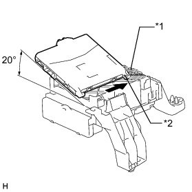
Text in Illustration
HINT
Be sure to maintain an angle of 20° or more as shown in the illustration.
(b) Slide the guide of the multiplex network body ECU along the housing sidewall toward the junction block fuses as shown in the illustration.
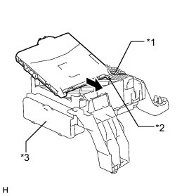
Text in Illustration
(c) Slide the multiplex network body ECU so that it contacts side A as shown in the illustration.
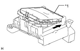
Text in Illustration

NOTICE:
Do not apply excessive force to the multiplex network body ECU.
(d) With the multiplex network body ECU contacting side A of the junction block (point of rotation), rotate it downward as shown in the illustration.
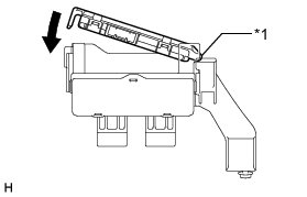
Text in Illustration

(e) Press the pushing area until the claw attaches to install the multiplex network body ECU.
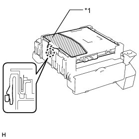
Text in Illustration

NOTICE:
* Make sure to press only the pushing area.
* Confirm the engagement of the multiplex network body ECU and junction block by listening for a lock sound.
* Do not apply excessive force to the multiplex network body ECU.
HINT
If a lock sound cannot be heard, visually check the engagement of the lock part. The engagement can also be confirmed if the multiplex network body ECU and junction block are flush.
2. INSTALL INSTRUMENT PANEL JUNCTION BLOCK ASSEMBLY
(a) Install the instrument panel junction block assembly with the 2 screws.
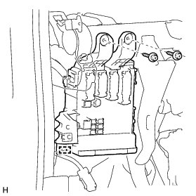
NOTICE:
Be sure to connect the connector securely.
(b) Attach the clamp.
(c) Connect the 6 connectors.
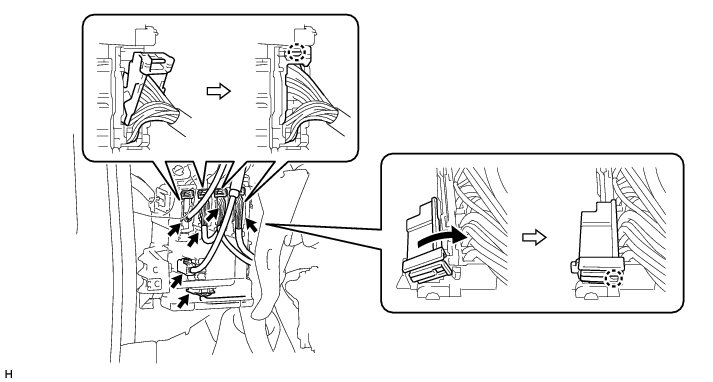
NOTICE:
Be sure to connect each connector securely.
(d) Attach the 5 claws.
3. INSTALL LOWER INSTRUMENT PANEL
(a) Install the lower instrument panel Installation.
4. INSTALL UPPER INSTRUMENT PANEL
Installation
5. CONNECT CABLE TO NEGATIVE BATTERY TERMINAL
NOTICE:
When disconnecting the cable, some systems need to be initialized after the cable is reconnected Repair Instruction - Initialization.
6. CHECK SRS WARNING LIGHT
Diagnosis System
Factory Service Tools
Use the Manual With the Right Hardware
Pair factory procedures with proven DIY tools so the instructions are easier to execute.
Disclosure: Verified tool recommendations may earn an affiliate commission at no cost to you.
When to See a Mechanic
Stop DIY work and contact a certified mechanic immediately if any of the following apply:
- • You smell fuel, burning insulation, or see smoke.
- • Brakes feel soft, pull hard to one side, or make grinding noises.
- • The engine overheats, stalls repeatedly, or misfires under load.
- • You are missing required tools, torque specs, or safe lifting equipment.
- • You are not confident in the next step or safety outcome.