
Safety Warning
DIY auto repair can cause serious injury, fire, or vehicle damage. These guides are for informational purposes only. Always follow OEM torque specs, wear PPE, and consult a certified mechanic if you are unsure. You are solely responsible for your safety.
2012 Scion tC L4-2.5L (2AR-FE)FACTORY OEM SERVICE PROCEDURE
CAN Communication System
NETWORKING: CAN COMMUNICATION SYSTEM: PRECAUTION
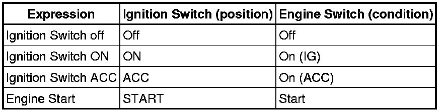
1. IGNITION SWITCH EXPRESSION
HINT
The type of ignition switch used on this model differs according to the specifications of the vehicle. The expressions listed in the table below are used in this section.
2. STEERING SYSTEM HANDLING PRECAUTIONS
(a) Care must be taken when replacing parts. Incorrect replacement could affect the performance of the steering system and result in hazards when driving.
3. SRS AIRBAG SYSTEM HANDLING PRECAUTIONS
(a) This vehicle is equipped with an SRS (Supplemental Restraint System), which includes components such as the driver airbag and front passenger side airbag. Failure to carry out service operations in the correct sequence could cause unexpected SRS deployment during servicing and may lead to a serious accident. Before servicing (including installation/removal, inspection and replacement of parts), be sure to read the precautionary notice for the Supplemental Restraint System Service Precautions.
4. BUS LINE REPAIR
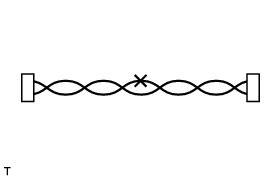
(a) After repairing the bus line with solder, wrap the repaired part with vinyl tape Electronic Circuit Inspection Procedure.
NOTICE:
* The CANL bus line and CANH bus line must be installed together.
* When installing the CAN bus lines, make sure to twist them.
* CAN bus lines are likely to be influenced by noise if the bus lines are not twisted together.
* The difference in length between the CANL bus line and CANH bus line should be less than 100 mm (3.94 in.).
* Leave approximately 80 mm (3.15 in.) loose in the twisted wires around the connectors.
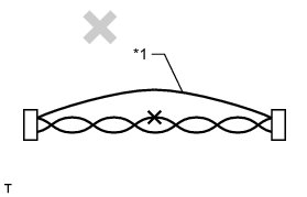
(b) Do not use by-pass wiring between the connectors.
NOTICE:
The protective effect of the twisted wire harness will be lost if bypass wiring is used.
Text in Illustration

5. CONNECTOR HANDLING
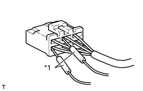
(a) When inserting probes into a connector, insert them from the rear of the connector.
Text in Illustration

(b) Use a repair wire to check the connector if it is impossible to check resistance from the rear of the connector.

Text in Illustration
Factory Service Tools
Use the Manual With the Right Hardware
Pair factory procedures with proven DIY tools so the instructions are easier to execute.
Disclosure: Verified tool recommendations may earn an affiliate commission at no cost to you.
When to See a Mechanic
Stop DIY work and contact a certified mechanic immediately if any of the following apply:
- • You smell fuel, burning insulation, or see smoke.
- • Brakes feel soft, pull hard to one side, or make grinding noises.
- • The engine overheats, stalls repeatedly, or misfires under load.
- • You are missing required tools, torque specs, or safe lifting equipment.
- • You are not confident in the next step or safety outcome.