
Safety Warning
DIY auto repair can cause serious injury, fire, or vehicle damage. These guides are for informational purposes only. Always follow OEM torque specs, wear PPE, and consult a certified mechanic if you are unsure. You are solely responsible for your safety.
2012 Porsche Boxster (987) F6-2.9LFACTORY OEM SERVICE PROCEDURE
Subframe: Service and Repair
WM 518941 Repairing threaded bushes for suspension subframe installation
Tools


Installing threaded bush
Installing repair threaded bush

Installation position of threaded bush for suspension subframe mount

NOTICE
Improper thread repairs
- Damaged thread
-> Thread repairs can only be carried out using the Time-Sert thread repair system.
Information
The repair bush must be installed recessed. Milling in may only be performed using the Porsche special tool contained in the Time-Sert thread repair kit.
Information
While pressing in the base thread, a noticeably larger amount of force is required on the screw-in tool to form the internal thread. Pressing is finished when the screw-in tool can be turned further more easily.
1. Drill out thread
Select M10 or M14 kit.
Drill out old thread as far as the base of the thread using a drill bit contained in the M10 or M14 kit B.

Drilling out thread
2. Mill in shoulder
Select M10 or M14 kit.
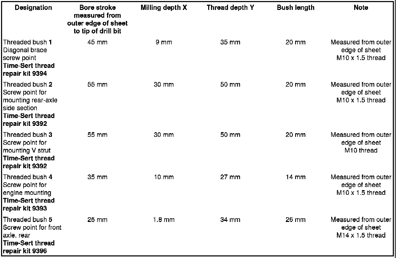
Mill out bore hole up to dimension X using spot facer C. See Table. Milling in may only be performed using the tool contained in the Porsche special tools. Use an electronically controlled power drill set to a speed of approx. 250 rpm (1/min) for milling in.

Milling in shoulder
3. Cut thread
Cut thread into the chassis bushing using a cutting tool D up to dimension Y. See Table ?????. Clean the thread on the chassis bushing (blow it out).

Cutting thread
4. Position threaded bush on the screw-in tool
Clean the thread on the bush and screw-in tool.
Oil the screw-in tool E.
Screw the threaded bush A onto the screw-in tool E by hand.

Positioning threaded bush on screw-in tool
5. Screw in threaded bush
Screw threaded bush A in fully (note bush length classification) using the screw-in tool E.

Screwing in threaded bush
6. Press threaded bush
Shape and press threaded bush E by turning further with the screw-in tool D in the base thread.

Pressing threaded bush
7. Unscrew screw-in tool
Unscrew screw-in tool E from the threaded bush A.
Table classification for suspension subframe repairs
-------------------------------------------------------------------------------
987110, 987111, 987120, 987121, 987140, 987141, 987160, 987161, 987310, 987311, 987320, 987321, 987330, 987340, 987360, 987361, 987371, 987381, 987720, 987721, 987740, 987741, 987130, 987180, 987181, 987350, 987760, 987761, 987780, 987781
Model year as of 2005
C00, C02, C05, C07, C08, C09, C10, C11, C12, C13, C14, C15, C16, C18, C19, C20, C21, C22, C23, C24, C25, C26, C27, C28, C32, C33, C34, C35, C36, C37, C38, C39, C45, C46, C98, C99
Factory Service Tools
Use the Manual With the Right Hardware
Pair factory procedures with proven DIY tools so the instructions are easier to execute.
Disclosure: Verified tool recommendations may earn an affiliate commission at no cost to you.
When to See a Mechanic
Stop DIY work and contact a certified mechanic immediately if any of the following apply:
- • You smell fuel, burning insulation, or see smoke.
- • Brakes feel soft, pull hard to one side, or make grinding noises.
- • The engine overheats, stalls repeatedly, or misfires under load.
- • You are missing required tools, torque specs, or safe lifting equipment.
- • You are not confident in the next step or safety outcome.