
Safety Warning
DIY auto repair can cause serious injury, fire, or vehicle damage. These guides are for informational purposes only. Always follow OEM torque specs, wear PPE, and consult a certified mechanic if you are unsure. You are solely responsible for your safety.
2008 Pontiac Grand Prix V6-3.8LFACTORY OEM SERVICE PROCEDURE
Body Control Module: Service and Repair
Body Control Module Replacement
Removal Procedure
Notice: Electrostatic discharge (ESD) can damage many solid-state electrical components. ESD susceptible components may or may not be labeled with the ESD symbol. Handle all electrical components carefully. Use the following precautions in order to avoid ESD damage:
* Touch a metal ground point in order to remove your body's static charge before servicing any electronic component; especially after sliding across the vehicle seat.
* Do not touch exposed terminals. Terminals may connect to circuits susceptible the ESD damage.
* Do not allow tools to contact exposed terminals when servicing connectors.
* Do not remove components from their protective packaging until required to do so.
* Avoid the following actions unless required by the diagnostic procedure:
- Jumpering or grounding of the components or connectors.
- Connecting test equipment probes to components or connectors. Connect the ground lead first when using test probes.
* Ground the protective packaging of any component before opening. Do not rest solid-state components on metal workbenches, or on top of TVs, radios, or other electrical devices.
Important: You must perform the new body control module (BCM) setup when replacing the BCM. Refer to Control Module References (Programming and Relearning) .
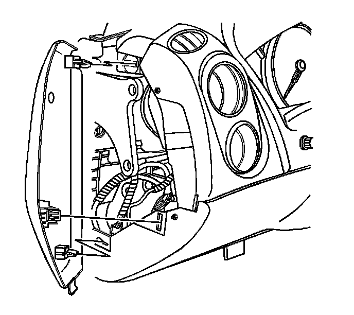
1. Pull the left instrument panel (I/P) compartment access hole cover from the I/P trim pad.
2. Press to release the cam lock. Disconnect the upper electrical connector from the BCM.
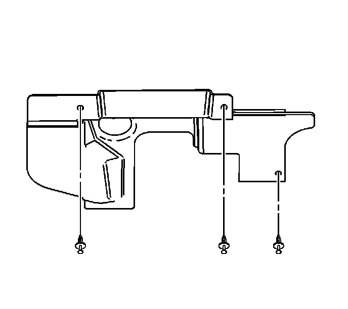
3. Remove the left I/P insulator fasteners.
4. Rotate the lamp. Remove the lamp from the insulator.
5. Remove the left I/P insulator.

6. Disengage the data link connector (DLC) retainers. Remove the DLC from the I/P trim pad.

7. Use a plastic trim tool to remove the ignition switch bezel.
8. Pull the I/P accessory trim plate rearward slightly for access to the steering column filler. Refer to Instrument Panel Accessory Trim Plate Replacement (Service and Repair) .
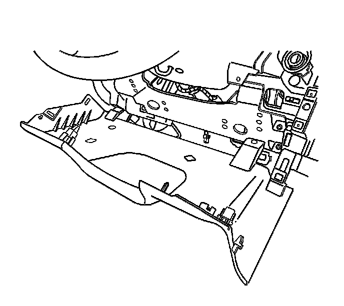
9. Remove the I/P steering column opening filler screws.
10. Pull the I/P steering column opening filler rearward. Remove the I/P steering column opening filler.
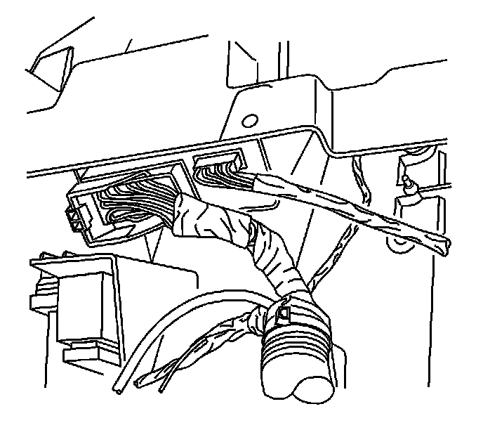
11. Press to release the cam lock. Disconnect the lower BCM electrical connectors.
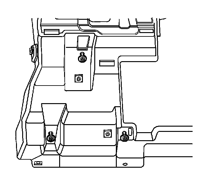
12. Remove the BCM screws.
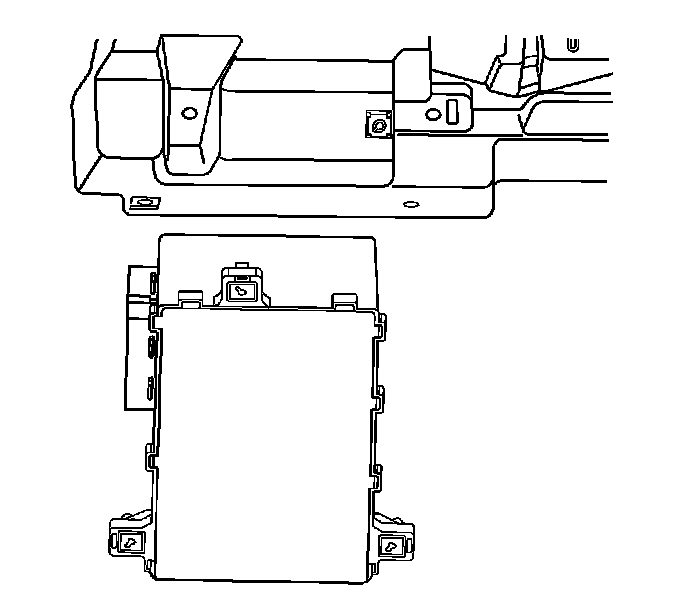
13. Remove the BCM.
Installation Procedure
1. Align the BCM to the I/P trim pad.
Notice: Refer to Fastener Notice (Fastener Notice) .
2. Install the BCM screws.
Tighten the screws to 2 N.m (18 lb in).
3. Connect the lower BCM electrical connectors. Engage the cam lock.
4. Align the I/P steering column opening filler to the I/P trim pad. Press the filler panel to the I/P trim pad.
5. Install the I/P steering column opening filler screws.
Tighten the screws to 2 N.m (18 lb in).
6. Install the I/P accessory trim plate. Refer to Instrument Panel Accessory Trim Plate Replacement (Service and Repair) .
7. Install the ignition switch bezel.
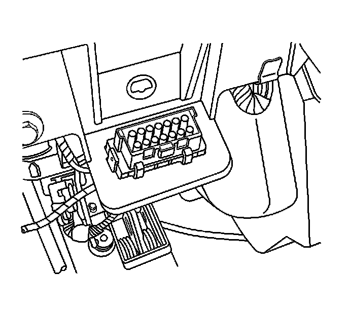
8. Align the DLC to the I/P trim pad. Install the DLC to the I/P trim pad.
9. Install the lamp to the left I/P insulator opening.
10. Align the left I/P insulator to the I/P trim pad.
11. Install the I/P insulator fasteners.
12. Connect the upper electrical connector to the BCM. Engage the cam lock.
13. Align the left I/P compartment access hole cover to the I/P trim pad. Press the I/P compartment access hole cover to the I/P trim pad.
14. Perform the new BCM setup. Refer to Control Module References (Programming and Relearning) .
Factory Service Tools
Use the Manual With the Right Hardware
Pair factory procedures with proven DIY tools so the instructions are easier to execute.
Disclosure: Verified tool recommendations may earn an affiliate commission at no cost to you.
When to See a Mechanic
Stop DIY work and contact a certified mechanic immediately if any of the following apply:
- • You smell fuel, burning insulation, or see smoke.
- • Brakes feel soft, pull hard to one side, or make grinding noises.
- • The engine overheats, stalls repeatedly, or misfires under load.
- • You are missing required tools, torque specs, or safe lifting equipment.
- • You are not confident in the next step or safety outcome.
Rather have a pro handle this?
A certified mobile mechanic comes to your home or office. They bring the tools, you stay comfortable. No tow truck, no waiting room, no surprises.
Comes to youSame-day available12-month warranty
Get a Free QuoteNo obligation. See pricing before you book.