
Safety Warning
DIY auto repair can cause serious injury, fire, or vehicle damage. These guides are for informational purposes only. Always follow OEM torque specs, wear PPE, and consult a certified mechanic if you are unsure. You are solely responsible for your safety.
2008 Pontiac G6 L4-2.4LFACTORY OEM SERVICE PROCEDURE
Control Assembly: Locations
Instrument Panel/Center Console Component Views
Lower Center and Right of the I/P Components
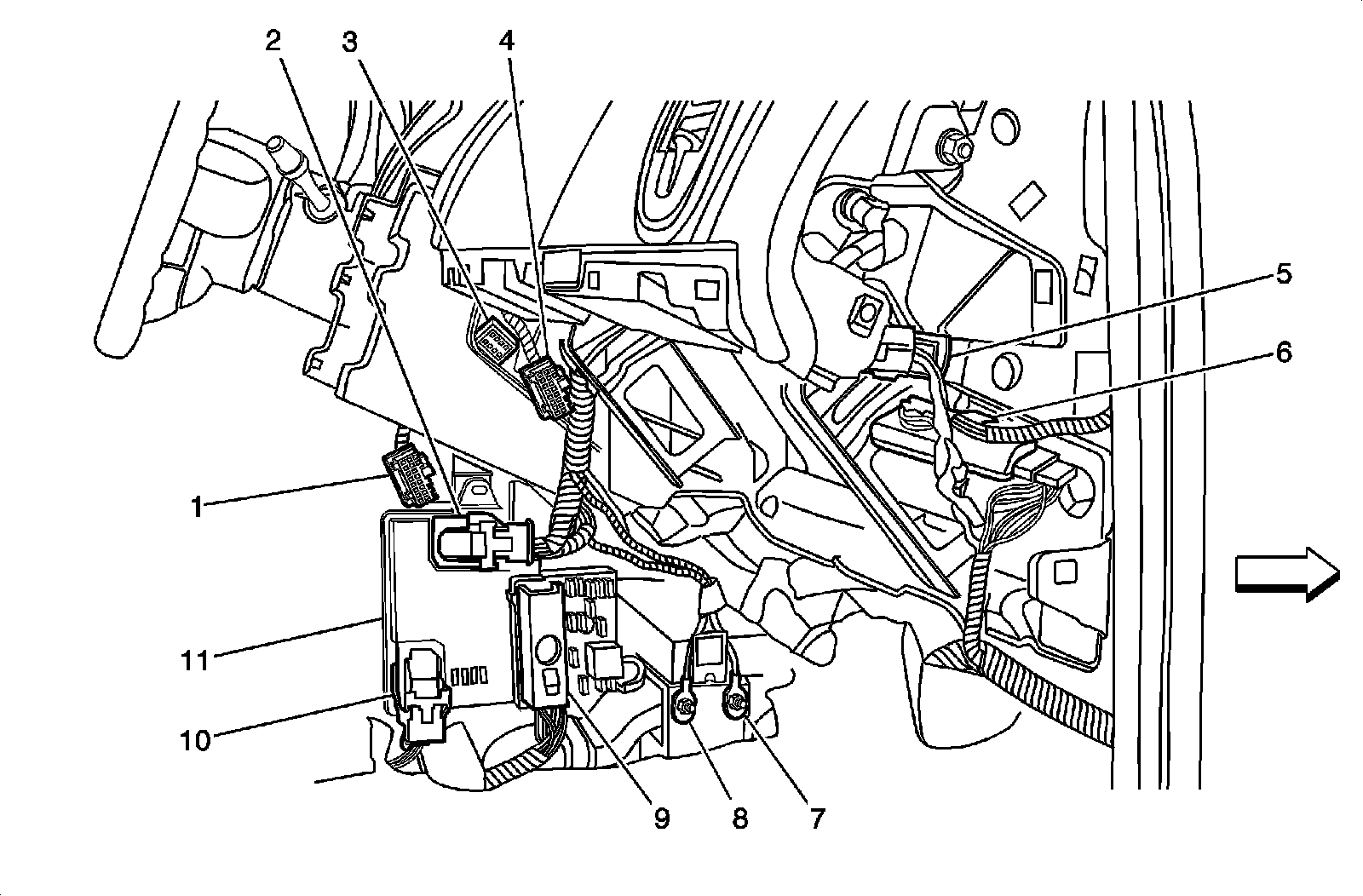
1 - Radio, X1
2 - Body Control Module (BCM), X2
3 - HVAC Control Module, X2
4 - HVAC Control Module, X1
5 - Inflatable Restraint I/P Module Connector
6 - X207
7 - G201
8 - G203
9 - Body Control Module (BCM), X3
10 - Body Control Module (BCM), X1
11 - Body Control Module (BCM)
I/P Components
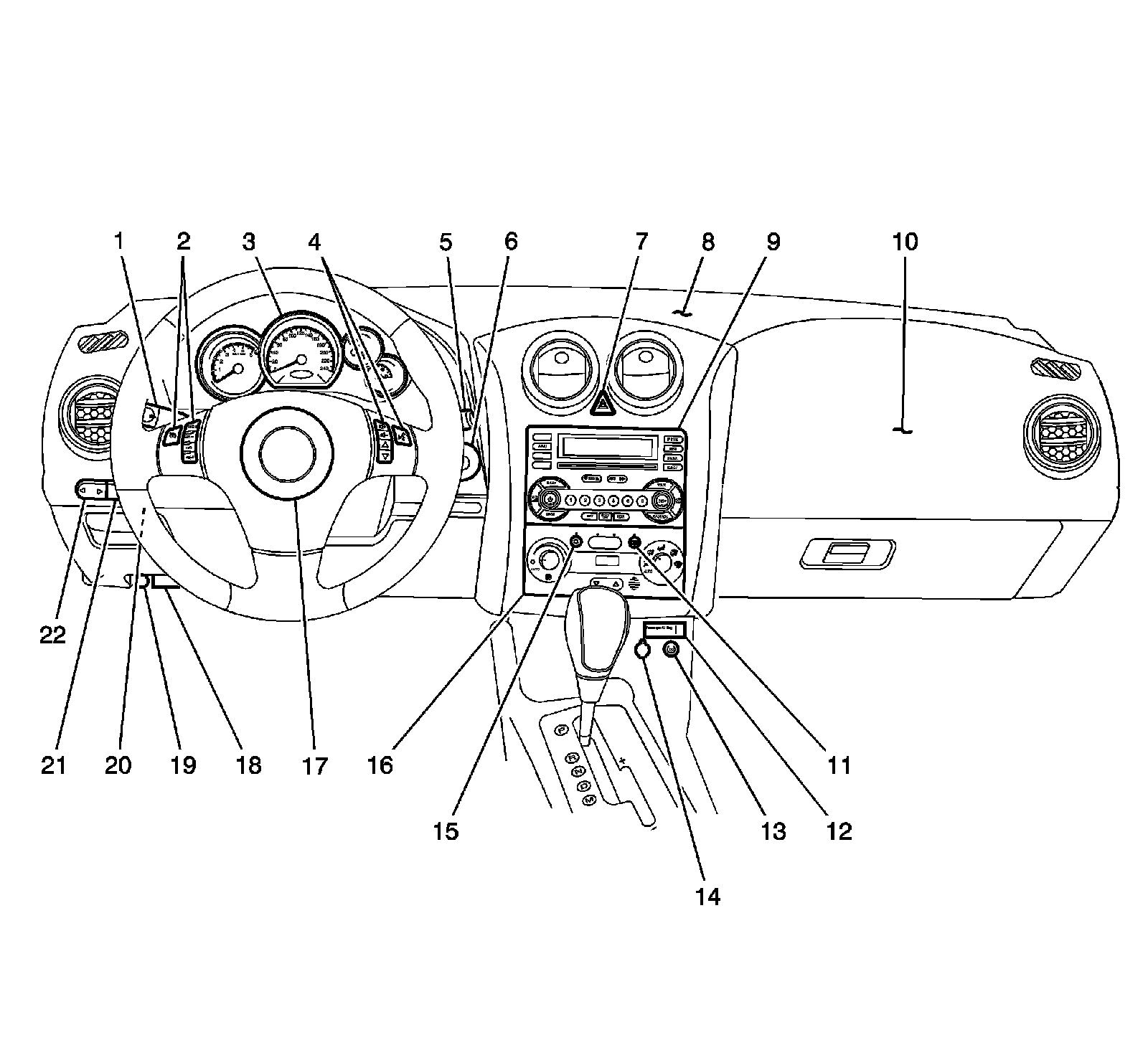
1 - Turn Signal/Multifunction Switch
2 - Steering Wheel Controls - Left
3 - Instrument Panel Cluster (IPC)
4 - Steering Wheel Controls - Right
5 - Windshield Wiper/Washer Switch
6 - Ignition Switch
7 - Hazard Switch
8 - Ambient Light Sensor (C60), Sunload Sensor (C68)
9 - Radio
10 - Inflatable Restraint I/P Module
11 - Rear Window Defogger Switch
12 - Inflatable Restraint PASSENGER AIR BAG ON/OFF Indicator
13 - Traction Control Switch (NW7/NW9)
14 - Cigar Lighter
15 - A/C Request Switch (C60)
16 - HVAC Control Module
17 - Inflatable Restraint Steering Wheel Module
18 - Data Link Connector (DLC)
19 - Accessory Power Outlet
20 - Fog Lamp Switch (T96)
21 - I/P Dimmer Switch
22 - Adjustable Pedal Position Switch (JF4)
Factory Service Tools
Use the Manual With the Right Hardware
Pair factory procedures with proven DIY tools so the instructions are easier to execute.
Disclosure: Verified tool recommendations may earn an affiliate commission at no cost to you.
When to See a Mechanic
Stop DIY work and contact a certified mechanic immediately if any of the following apply:
- • You smell fuel, burning insulation, or see smoke.
- • Brakes feel soft, pull hard to one side, or make grinding noises.
- • The engine overheats, stalls repeatedly, or misfires under load.
- • You are missing required tools, torque specs, or safe lifting equipment.
- • You are not confident in the next step or safety outcome.