
Safety Warning
DIY auto repair can cause serious injury, fire, or vehicle damage. These guides are for informational purposes only. Always follow OEM torque specs, wear PPE, and consult a certified mechanic if you are unsure. You are solely responsible for your safety.
2008 Pontiac G5 L4-2.2LFACTORY OEM SERVICE PROCEDURE
Front Subframe: Service and Repair
Frame Replacement
Tools Required
* J 24319-B Steering Linkage and Tie Rod Puller
* J 43631 Ball Joint Remover
Removal Procedure
1. With the wheels in the straight ahead position, remove the key from the ignition switch.
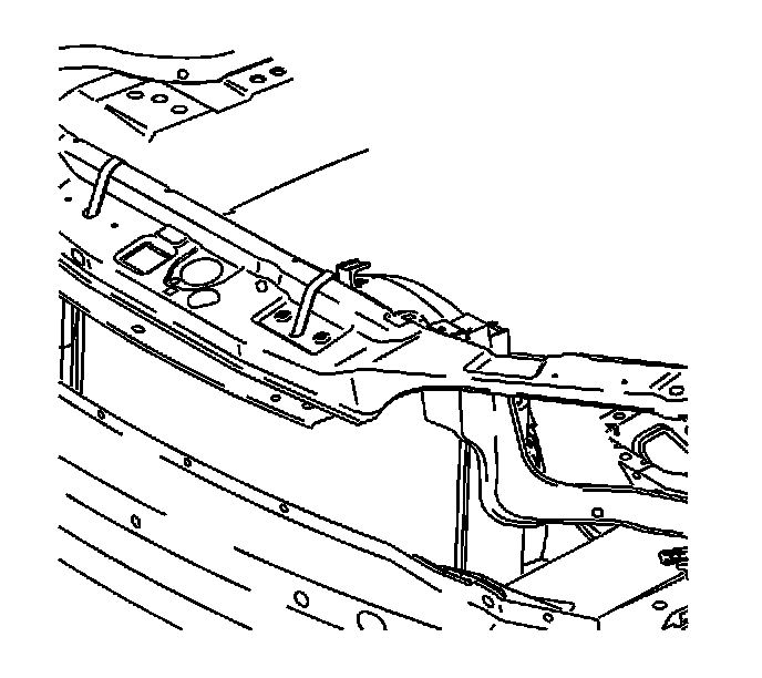
2. Secure the cooling module to the upper body structure.
3. Raise and support the vehicle. Refer to Vehicle Lifting.
4. Remove the front wheels from the vehicle.
5. Remove the left and right splash shields and the 3 screws in the inner fenders.
6. Remove the lower radiator air deflector from the frame.
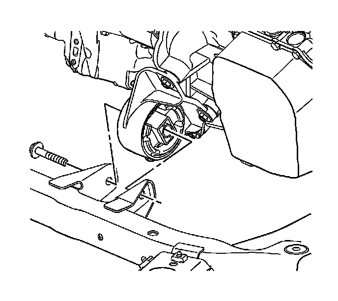
7. Remove the front transaxle mount to frame through bolt.
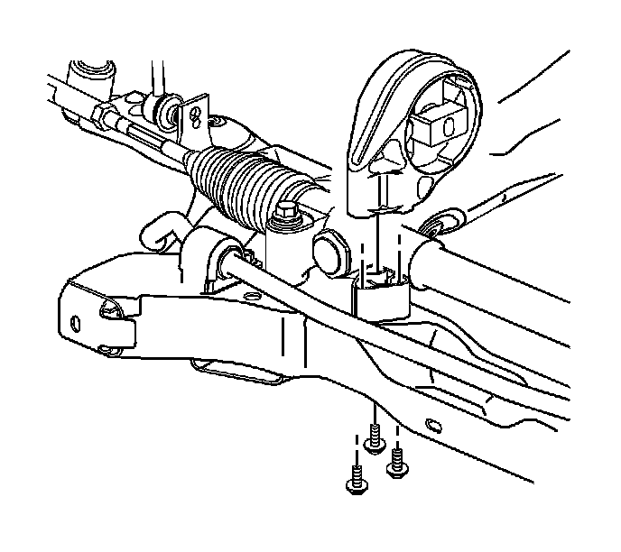
8. Remove the rear transaxle mount to frame bolts.
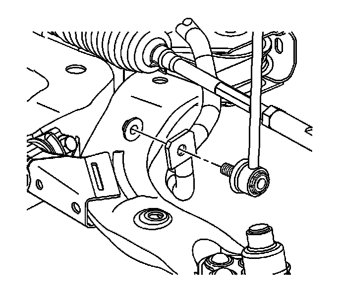
9. Remove both stabilizer link to stabilizer shaft nuts.
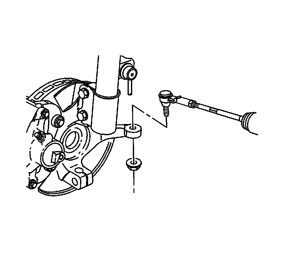
10. Remove both tie rod to steering knuckle nuts.

11. Use the J 24319-B to separate the outer tie rods from the steering knuckles.

12. Remove the intermediate steering shaft to steering gear pinch bolt and discard.
Important: DO NOT rotate the intermediate shaft once separated from the gear. Possible damage or a malfunction could occur.
13. Disconnect the intermediate steering shaft from the steering gear.
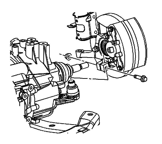
14. Remove both lower control arm ball stud to steering knuckle pinch bolts.
Notice: Do not free the ball stud by using a pickle fork or a wedge-type tool. Damage to the seal or bushing may result.
15. Lower the lower control arms in order to disengage the steering knuckle. If necessary, use the J 43631.
16. Mark the frame to body position with a paint pen or permanent marker.
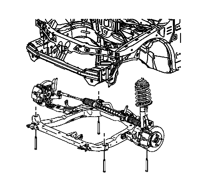
17. Lower the vehicle to approximately 1 meter (3 feet) off the ground in order to place a hydraulic lift table under the frame.
18. Use two 2 x 4s between the lift table and the frame and lift the table to the frame.
19. Slowly remove the frame bolts using the following sequence:
1. Remove the front frame bolts.
2. Remove the rear frame bolts.
20. Slowly lower the lift table and frame to the floor.
21. Continue with the following steps when replacing the frame:
1. Remove the steering gear from the frame.
2. Remove the stabilizer bar from the frame.
3. Remove the lower control arms from the frame.
4. Remove the radiator brackets from the frame.
Installation Procedure
1. If replacing the frame, perform the following steps:
1. Install the radiator brackets to the frame.
2. Install the lower control arms to the frame.
3. Install the stabilizer bar to the frame.
4. Install the steering gear to the frame.
2. With the frame on the lift table, raise the frame to the vehicle.
3. Hand start all the frame bolts while aligning the frame to the paint marks.
Notice: Refer to Fastener Notice.
4. Tighten the frame bolts.
Tighten the bolts to 100 N.m (74 lb ft) plus 180 degrees.
5. Lower and remove the hydraulic table.
6. Connect the lower control arm to the steering knuckle.
Important: The torque sequence must be followed in the order that is listed.
7. Install the ball joint pinch bolt and nut.
1. First Pass-Tighten the nut to 50 N.m (37 lb ft).
2. Reverse the nut 3/4 turn.
3. Second Pass-Tighten the nut to 50 N.m (37 lb ft) plus 30 degrees.
Important: The front and rear transmission mounts must be allowed to settle with the through bolts loosened.
8. Hand start the front transaxle mount through bolt.
9. Loosen the rear transmission mount through bolt.
10. Tighten the rear transaxle mount to frame bolts.
Tighten the rear bolts to 50 N.m (37 lb ft).
11. Tighten the front and rear transaxle mount through bolts in the following order.
1. Tighten the rear bolt to 100 N.m (74 lb ft).
2. Tighten the front bolt to 100 N.m (74 lb ft).
12. Install the outer tie rods to the steering knuckles.
13. Install the new outer tie rod to the knuckle nuts.
Tighten the nuts to 20 N.m (15 lb ft) plus 180 degrees.
14. Connect the stabilizer links to the stabilizer shaft.
15. Connect the intermediate shaft to the steering gear.
16. Install a new intermediate shaft pinch bolt.
Tighten the bolt to 34 N.m (25 lb ft).
17. Install the left and right splash shields and the 3 inner fender screws.
18. Install the lower radiator air deflector to the frame.
19. Install the front wheels.
20. Lower the vehicle.
21. Road test the vehicle in order to test for the following conditions:
* Steering leads or pulls-Refer to Wheel Alignment Measurement.
* Abnormal powertrain noise or vibration at idle-Inspect the engine and transmission mounts for proper alignment and torque.
Factory Service Tools
Use the Manual With the Right Hardware
Pair factory procedures with proven DIY tools so the instructions are easier to execute.
Disclosure: Verified tool recommendations may earn an affiliate commission at no cost to you.
When to See a Mechanic
Stop DIY work and contact a certified mechanic immediately if any of the following apply:
- • You smell fuel, burning insulation, or see smoke.
- • Brakes feel soft, pull hard to one side, or make grinding noises.
- • The engine overheats, stalls repeatedly, or misfires under load.
- • You are missing required tools, torque specs, or safe lifting equipment.
- • You are not confident in the next step or safety outcome.
Rather have a pro handle this?
A certified mobile mechanic comes to your home or office. They bring the tools, you stay comfortable. No tow truck, no waiting room, no surprises.
Comes to youSame-day available12-month warranty
Get a Free QuoteNo obligation. See pricing before you book.