
Safety Warning
DIY auto repair can cause serious injury, fire, or vehicle damage. These guides are for informational purposes only. Always follow OEM torque specs, wear PPE, and consult a certified mechanic if you are unsure. You are solely responsible for your safety.
2007 Pontiac G6 L4-2.4LFACTORY OEM SERVICE PROCEDURE
Window Frame: Service and Repair
Windshield Frame Header Panel Replacement - Front
REMOVAL PROCEDURE
CAUTION: Refer to Approved Equipment for Collision Repair Caution.

1. Disable the SIR system. Refer to SIR Disabling and Enabling Zones.
CAUTION: Refer to Battery Disconnect Caution.
2. Disconnect the negative battery cable.
3. Remove all related panels and components.
4. Repair as much of the damaged area as possible.
5. Remove the sealers and anti-corrosion materials from the repair area, as necessary. Refer to Anti-Corrosion Treatment and Repair.
IMPORTANT: Note the number and location of the factory welds for installation of the header panel.
6. Locate and drill out all the necessary factory welds.
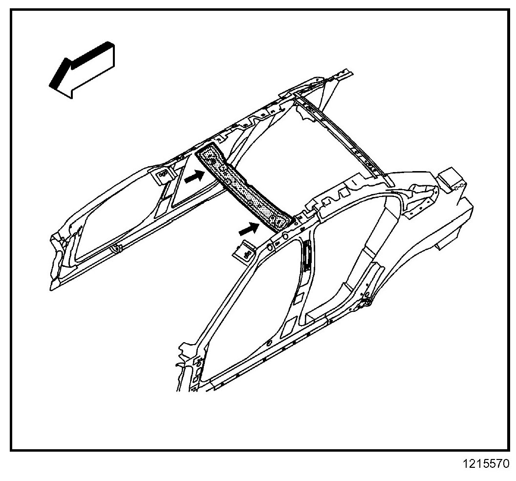
7. Remove the header panel.
INSTALLATION PROCEDURE
IMPORTANT: If the location of the original plug weld holes can not be determined, space the plug weld holes every 40 mm (1 1/2 in) apart.
1. Drill 8 mm (5/16 in) plug weld holes in the service part as necessary in the locations noted from the original panel.
2. Prepare all mating surfaces as necessary.
3. Apply 3M(R) Weld-Thru coating P/N 05916 or equivalent to all mating surfaces.
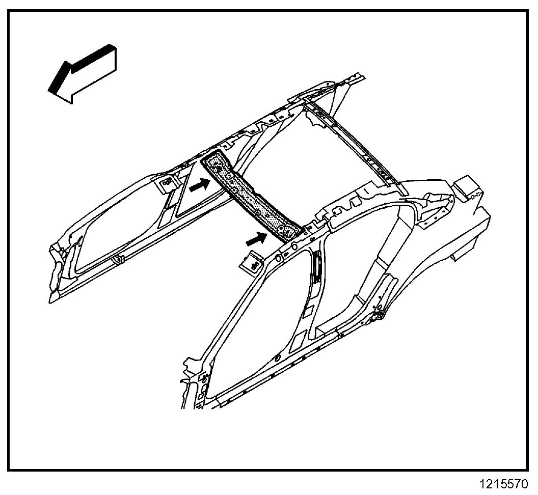
4. Position the header panel to the vehicle using 3-dimensional measuring equipment. Clamp the front header panel in place.
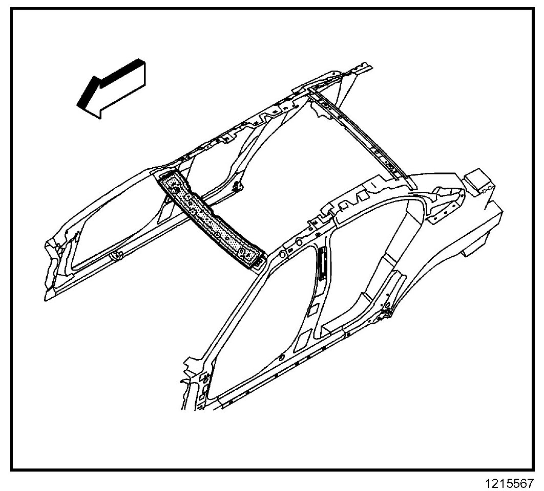
5. Plug weld accordingly.
6. Clean and prepare all of the welded surfaces.
7. Install all of the related panels and components.
8. Apply the sealers and anti-corrosion materials to the repair area, as necessary. Refer to Anti-Corrosion Treatment and Repair.
9. Paint the repaired area.
CAUTION: Refer to Battery Disconnect Caution.
10. Connect the negative battery cable.
11. Enable the SIR system. Refer to SIR Disabling and Enabling Zones.
REMOVAL PROCEDURE
CAUTION: Refer to Approved Equipment for Collision Repair Caution.
1. Disable the SIR system. Refer to SIR Disabling and Enabling Zones.
CAUTION: Refer to Battery Disconnect Caution.
2. Disconnect the negative battery cable.
3. Remove all related panels and components.
4. Repair as much of the damaged area as possible.
5. Remove the sealers and anti-corrosion materials from the repair area, as necessary. Refer to Anti-Corrosion Treatment and Repair.
IMPORTANT: Note the number and location of the factory welds for installation of the header panel.
6. Locate and drill out all the necessary factory welds.
7. Remove the header panel.
INSTALLATION PROCEDURE
IMPORTANT: If the location of the original plug weld holes can not be determined, space the plug weld holes every 40 mm (1 1/2 in) apart.
1. Drill 8 mm (5/16 in) plug weld holes in the service part as necessary in the locations noted from the original panel.
2. Prepare all mating surfaces as necessary.
3. Apply 3M(R) Weld-Thru coating P/N 05916 or equivalent to all mating surfaces.
4. Position the header panel to the vehicle using 3-dimensional measuring equipment. Clamp the front header panel in place.
5. Plug weld accordingly.
6. Clean and prepare all of the welded surfaces.
7. Install all of the related panels and components.
8. Apply the sealers and anti-corrosion materials to the repair area, as necessary. Refer to Anti-Corrosion Treatment and Repair.
9. Paint the repaired area.
CAUTION: Refer to Battery Disconnect Caution.
10. Connect the negative battery cable.
11. Enable the SIR system. Refer to SIR Disabling and Enabling Zones.
Factory Service Tools
Use the Manual With the Right Hardware
Pair factory procedures with proven DIY tools so the instructions are easier to execute.
Disclosure: Verified tool recommendations may earn an affiliate commission at no cost to you.
When to See a Mechanic
Stop DIY work and contact a certified mechanic immediately if any of the following apply:
- • You smell fuel, burning insulation, or see smoke.
- • Brakes feel soft, pull hard to one side, or make grinding noises.
- • The engine overheats, stalls repeatedly, or misfires under load.
- • You are missing required tools, torque specs, or safe lifting equipment.
- • You are not confident in the next step or safety outcome.