
Safety Warning
DIY auto repair can cause serious injury, fire, or vehicle damage. These guides are for informational purposes only. Always follow OEM torque specs, wear PPE, and consult a certified mechanic if you are unsure. You are solely responsible for your safety.
2005 Pontiac Vibe FWD L4-1.8L VIN 8FACTORY OEM SERVICE PROCEDURE
1. Transaxle Disassemble
Transaxle Disassemble
^ Tools Required
- J 35451 Reverse Light Switch Socket
- J 8001 Dial Indicator
- J 26900-13 Magnetic Base
- J 22912-01Split - Plate Bearing Puller
- J 1859-A Steering Wheel Puller
- J 8433-1 Puller Bar
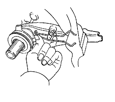
1. Remove the clutch release fork and the clutch release bearing.
2. Remove one retaining bolt and remove the vehicle speed sensor (VSS) from the transaxle case.
3. Use the J 35451 to remove the backup switch.
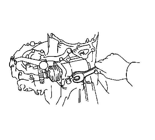
4. Remove the selecting bellcrank.
5. Remove the lock bolt.
6. Remove the shift and select lever assembly.
7. Remove the engage gears.
8. Remove the fifth gear lock nut.
9. Remove the disengage gears.
10. Remove the case side cover bolts.
11. Remove the case side cover.
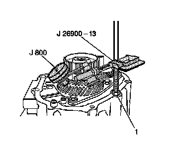
12. Use the J 8001 with the J 26900-13 to measure the fifth gear thrust clearance. If the clearance is not 0.10 - 0.65 mm (0.0039 - 0.0256 inch), you must use a selective snap ring on reassembly.
13. Remove the fifth gear shift fork lock bolt.
14. Remove the fifth gear shift fork and synchronizer shift sleeve.
15. Remove the fifth gear synchronizer snap ring.
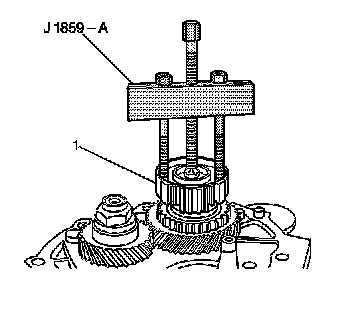
16. Attach the J 1859-A to the fifth gear synchronizer hub.
17. Use the J 1859-A to remove the fifth gear synchronizer hub (1).
18. Remove the following components:
^ The synchronizer blocking ring
^ The needle roller bearing
^ The spacer
^ The fifth gear driven gear
19. Unstake the fifth drive gear lock nut.
20. Remove the fifth drive gear lock nut.
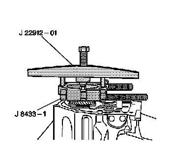
21. Attach the J 22912-01 and the J 8433-1 to the fifth drive gear.
22. Use the J 22912-01 and the J 8433-1 to remove the fifth drive gear.
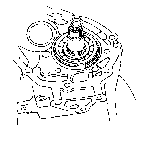
23. Remove the following components:
^ The needle roller bearing
^ The spacer
24. Remove the rear bearing retainer.
25. Remove two bearing snap rings.
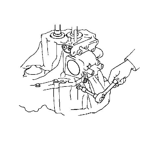
26. Remove the reverse idler gear shaft lock bolt.
27. Use two screwdrivers and a hammer to remove the snap ring from the number 2 shift fork shaft.
28. Remove the following components:
^ Three plugs
^ The lock bolt
^ The lock bolt assembly

29. Use a magnetic finger to remove the following components:
^ Three seats
^ The springs
^ The balls

30. Remove the case cover by removing 16 bolts.
31. Carefully pry the case halves apart (1).
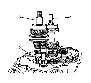
32. Remove the reverse shift arm bracket.
33. Remove the following components:
^ The reverse idler gear (2)
^ The thrust washer
^ The shaft

34. Use two screwdrivers and a hammer to remove three snap rings. Remove 3 set bolts from the shift forks.
35. Remove the following components:
^ The number 2 shift fork shaft
^ The shift head
36. Use a magnetic finger to remove the two balls.
37. Remove the following components:
^ The number 3 shift fork shaft
^ The reverse shift fork
38. Pull out the number 1 shift fork shaft.
39. Remove the following components:
^ The number 1 shift fork shaft
^ The number 2 shift fork shaft
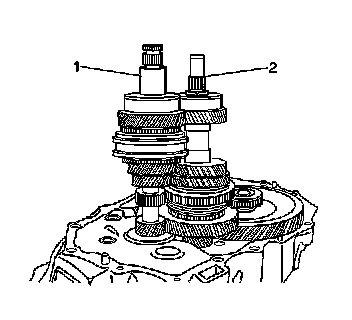
40. Remove the following components together:
^ The input shaft (1)
^ The output shaft (2)
41. Remove the differential assembly.
42. Remove the following components:
^ The magnet
^ The oil receiver
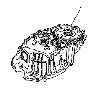
43. Remove the differential assembly (1).
44. Remove the following components:
^ The magnet
^ The oil receiver
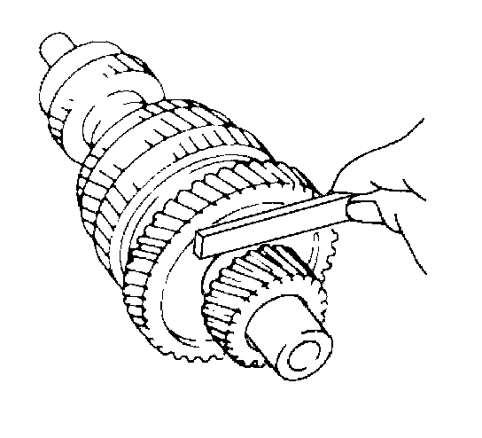
45. Use a feeler gage to measure the first gear thrust clearance. If the clearance is not 0.10 - 0.45 mm (0.0039 - 0.0177 inch), replace both of the following components:
^ The first gear
^ The second gear
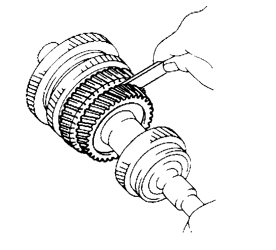
46. Use a feeler gage to measure the second gear thrust clearance. If clearance is not 0.10 - 0.50 mm (0.0039 - 0.0197 inch), replace both of the following components:
^ The second gear
^ The third gear
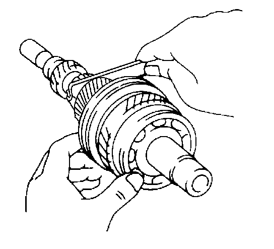
47. Use a feeler gage to measure the third gear thrust clearance. If the clearance is not 0.10 - 0.40 mm (0.0039 - 0.0157 inch), replace both of the following components:
^ The third gear
^ The fourth gear
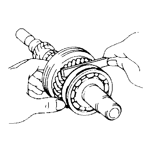
48. Use a feeler gage to measure the fourth gear thrust clearance. If the clearance is not 0.10 - 0.60 mm (0.0039 - 0.0236 inch) replace both of the following components:
^ The fourth gear
^ The fifth gear
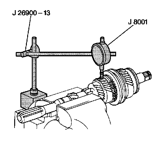
49. With the needle roller bearing installed, use a J 8001 to measure the oil clearance between the gear and the input shaft. If the clearance is not 0.015 - 0.070 mm (0.0006 - 0.0028 inch), replace the gear, the needle roller bearing, or the shaft.

50. Remove the snap ring from the input shaft.

51. Use a J 22912-01 with a press to remove the radial ball bearing.
52. Remove the following components:
^ The fourth gear
^ The needle roller bearing
^ The synchronizer ring
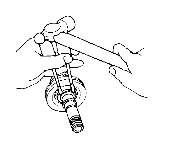
53. Remove the snap ring from the shaft.
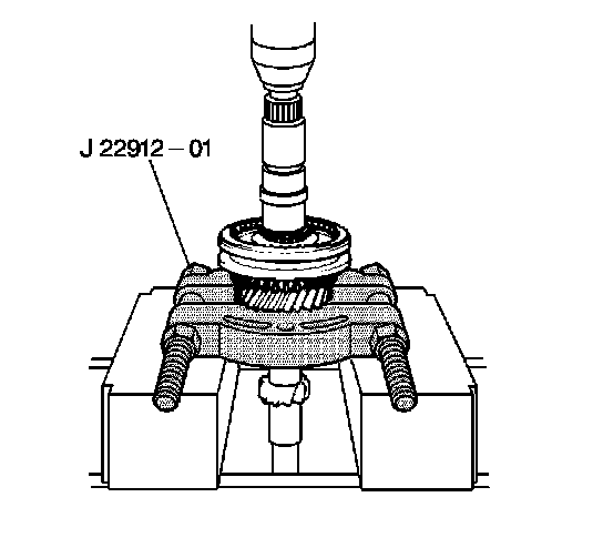
54. Use a J 22912-01 with a press to remove the following components:
^ The number 2 hub sleeve
^ The third gear synchronizer ring
^ The needle roller bearing
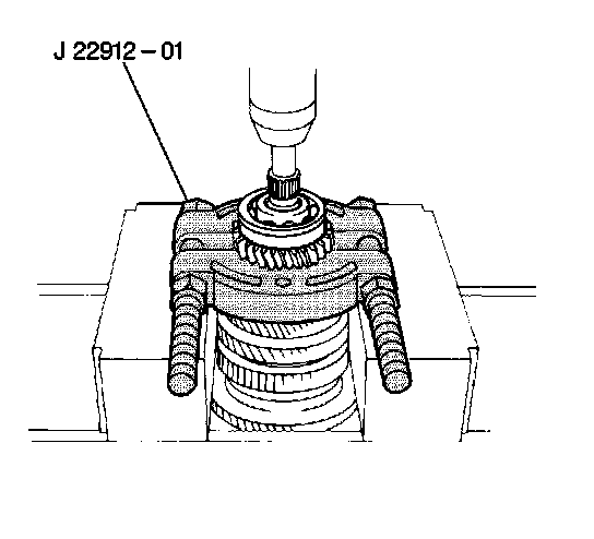
55. Use a J 22912-01 with a press to remove the following components:
^ The radial ball bearing
^ The fourth driver gear
56. Remove the spacer.
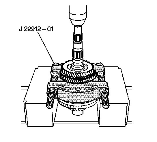
57. Remove the shift number 1 hub sleeve into the first gear.
58. Use a J 22912-01 with a press to remove the following components:
^ The third driven gear
^ The second gear
59. Remove the following components:
^ The needle roller bearing
^ The spacer
^ The synchronizer ring
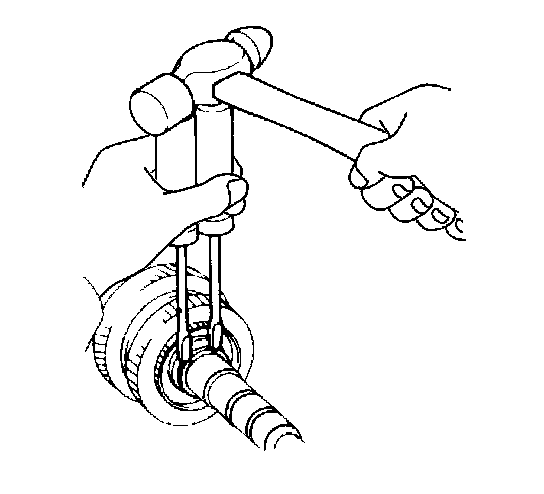
60. Remove the snap ring number 1 hub sleeve assembly.
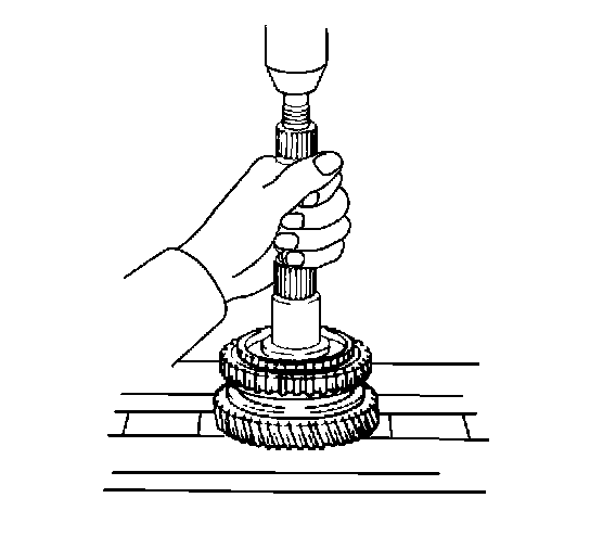
61. Use a press to remove the following components:
^ The number 1 hub
^ The first gear
^ The synchronizer ring
62. Remove the following components:
^ needle roller bearing
^ The thrust washer
^ The locking ball
Factory Service Tools
Use the Manual With the Right Hardware
Pair factory procedures with proven DIY tools so the instructions are easier to execute.
Disclosure: Verified tool recommendations may earn an affiliate commission at no cost to you.
When to See a Mechanic
Stop DIY work and contact a certified mechanic immediately if any of the following apply:
- • You smell fuel, burning insulation, or see smoke.
- • Brakes feel soft, pull hard to one side, or make grinding noises.
- • The engine overheats, stalls repeatedly, or misfires under load.
- • You are missing required tools, torque specs, or safe lifting equipment.
- • You are not confident in the next step or safety outcome.
Rather have a pro handle this?
A certified mobile mechanic comes to your home or office. They bring the tools, you stay comfortable. No tow truck, no waiting room, no surprises.
Comes to youSame-day available12-month warranty
Get a Free QuoteNo obligation. See pricing before you book.