
Safety Warning
DIY auto repair can cause serious injury, fire, or vehicle damage. These guides are for informational purposes only. Always follow OEM torque specs, wear PPE, and consult a certified mechanic if you are unsure. You are solely responsible for your safety.
2004 Pontiac Vibe AWD L4-1.8L VIN 8FACTORY OEM SERVICE PROCEDURE
Engine Control Module: Service and Repair
POWERTRAIN CONTROL MODULE (PCM) REPLACEMENT
REMOVAL PROCEDURE
NOTE:
- Check the resistance values of all PCM relays, solenoids, and other output controls before replacing or substituting the Powertrain Control Module (PCM). Check all the sensor wiring and the PCM output control circuits for a short to ground before replacing or substituting the PCM Perform all circuit repairs or malfunctioning component part replacements before installing a replacement or substitute PCM. This will prevent damage to the replacement or substitute PCM.
- Do not touch the connector pins or soldered components on the circuit board in order to prevent possible electrostatic discharge (ESD) damage to the PCM.
- Turn the ignition OFF when installing or removing the PCM connectors and disconnecting or reconnecting the power to the PCM (battery cable, PCM pigtail, PCM fuse, jumper cables, etc.) in order to prevent internal PCM damage.
IMPORTANT: Service of the powertrain control module (PCM) consists of a complete replacement of the PCM. There are no serviceable parts, such as programmable read-only memory (PROM) or erasable programmable read-only memory (EPROM) to replace inside the PCM. If the PCM is determined to be faulty, the PCM is to be replaced as a complete assembly.
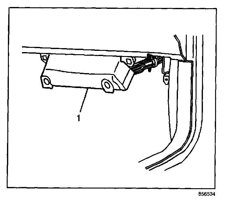
1. Disable the supplemental inflatable restraint (SIR) system. Refer to SIR Disabling and Enabling Zones in Restraint Systems.
2. Remove the two retainers from the PCM close out panel (1) below the instrument panel (IP) compartment door.
3. Swing the PCM close out panel (1) down.
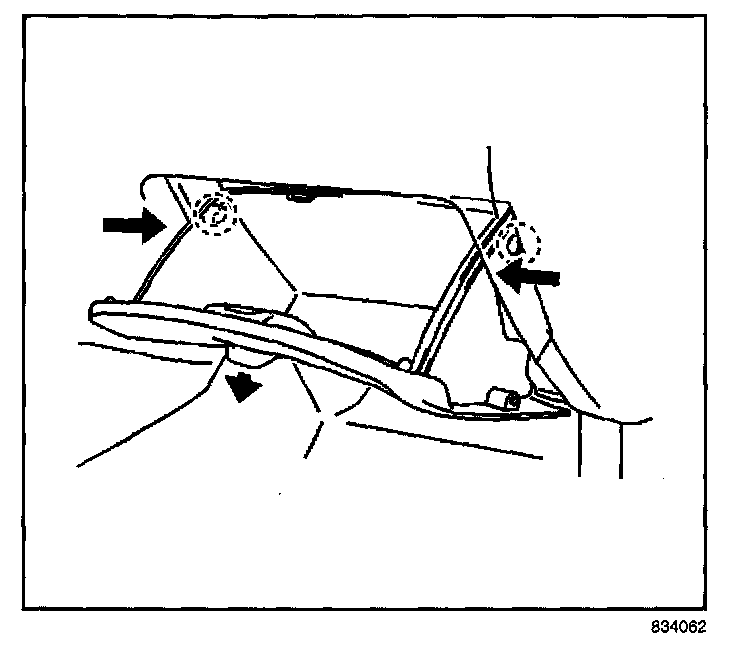
4. Open the IP compartment.
5. Push in on both sides of the IP compartment in order to release the safety catches.
6. Remove the IP compartment door assembly from the IP.
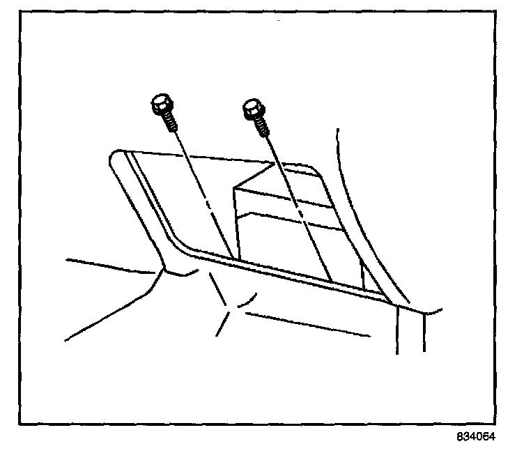
7. Remove the two PCM bracket fasteners.
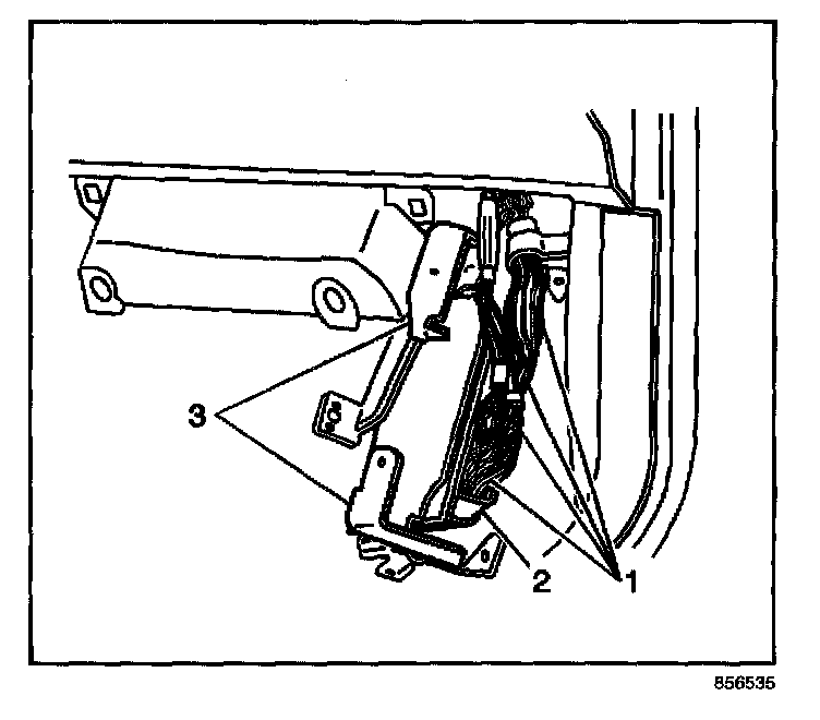
8. Pull the PCM (2) with brackets (3) toward you and swing both down away from under the IP.
9. Disconnect the four PCM electrical connectors (1).
10. Remove the four fasteners and the two brackets (3) from the PCM (2).
INSTALLATION PROCEDURE
NOTE:
- Do not touch the connector pins or soldered components on the circuit board in order to prevent possible electrostatic discharge (ESD) damage to the PCM.
- Turn the ignition OFF when installing or removing the PCM connectors and disconnecting or reconnecting the power to the PCM (battery cable, PCM pigtail, PCM fuse, jumper cables, etc.) in order to prevent internal PCM damage.
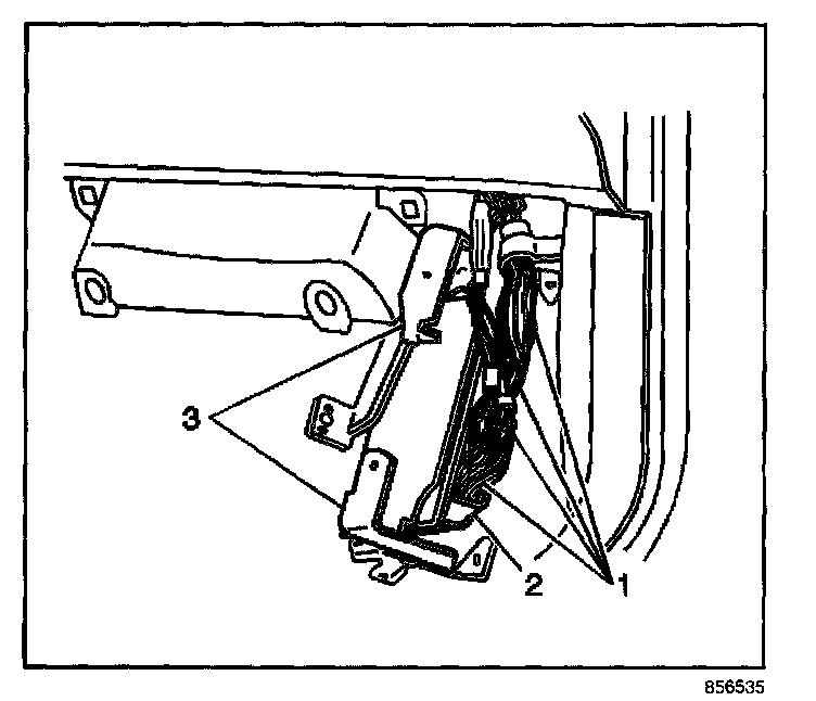
1. Install the two PCM brackets (3) to the PCM (2).
NOTE: Refer to Fastener Notice in Service Precautions.
2. Secure the two brackets to the PCM with the four fasteners.
Tighten
Tighten the PCM bracket fasteners to 3.2 N.m (28 lb in).
3. Connect the four PCM electrical connectors (1).
4. Swing the PCM (2) with bracket (3) up in position under the IP.
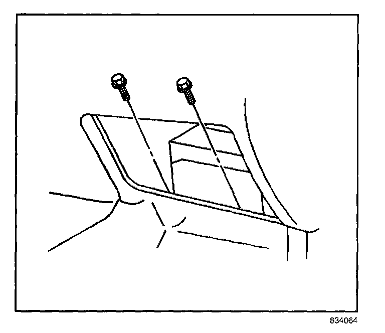
5. Secure the PCM to the IP with the two fasteners.
Tighten
Tighten the two fasteners to 9 N.m (80 lb in).
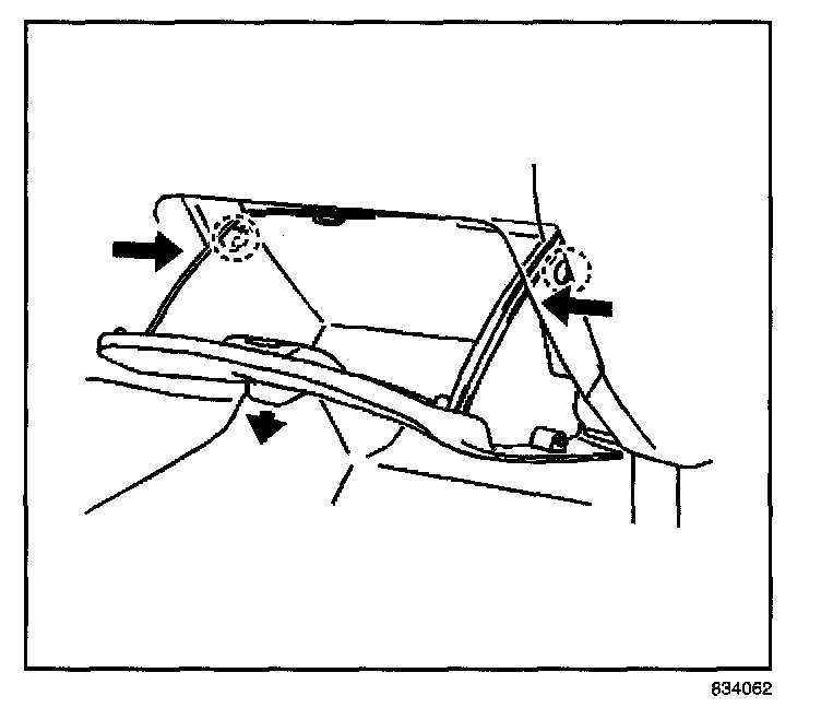
6. Install the IP compartment door into the IP.
7. Push in on both sides of the IP compartment in order to release the safety catches and close the door.
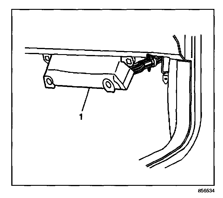
8. Swing the close out panel (1) up under the PCM and secure with the two retainers.
9. Enable the SIR system. Refer to SIR Disabling and Enabling Zones in Restraint Systems.
REMOVAL PROCEDURE
NOTE:
- Check the resistance values of all PCM relays, solenoids, and other output controls before replacing or substituting the Powertrain Control Module (PCM). Check all the sensor wiring and the PCM output control circuits for a short to ground before replacing or substituting the PCM Perform all circuit repairs or malfunctioning component part replacements before installing a replacement or substitute PCM. This will prevent damage to the replacement or substitute PCM.
- Do not touch the connector pins or soldered components on the circuit board in order to prevent possible electrostatic discharge (ESD) damage to the PCM.
- Turn the ignition OFF when installing or removing the PCM connectors and disconnecting or reconnecting the power to the PCM (battery cable, PCM pigtail, PCM fuse, jumper cables, etc.) in order to prevent internal PCM damage.
IMPORTANT: Service of the powertrain control module (PCM) consists of a complete replacement of the PCM. There are no serviceable parts, such as programmable read-only memory (PROM) or erasable programmable read-only memory (EPROM) to replace inside the PCM. If the PCM is determined to be faulty, the PCM is to be replaced as a complete assembly.
1. Disable the supplemental inflatable restraint (SIR) system. Refer to SIR Disabling and Enabling Zones in Restraint Systems.
2. Remove the two retainers from the PCM close out panel (1) below the instrument panel (IP) compartment door.
3. Swing the PCM close out panel (1) down.
4. Open the IP compartment.
5. Push in on both sides of the IP compartment in order to release the safety catches.
6. Remove the IP compartment door assembly from the IP.
7. Remove the two PCM bracket fasteners.
8. Pull the PCM (2) with brackets (3) toward you and swing both down away from under the IP.
9. Disconnect the four PCM electrical connectors (1).
10. Remove the four fasteners and the two brackets (3) from the PCM (2).
INSTALLATION PROCEDURE
NOTE:
- Do not touch the connector pins or soldered components on the circuit board in order to prevent possible electrostatic discharge (ESD) damage to the PCM.
- Turn the ignition OFF when installing or removing the PCM connectors and disconnecting or reconnecting the power to the PCM (battery cable, PCM pigtail, PCM fuse, jumper cables, etc.) in order to prevent internal PCM damage.
1. Install the two PCM brackets (3) to the PCM (2).
NOTE: Refer to Fastener Notice in Service Precautions.
2. Secure the two brackets to the PCM with the four fasteners.
Tighten
Tighten the PCM bracket fasteners to 3.2 N.m (28 lb in).
3. Connect the four PCM electrical connectors (1).
4. Swing the PCM (2) with bracket (3) up in position under the IP.
5. Secure the PCM to the IP with the two fasteners.
Tighten
Tighten the two fasteners to 9 N.m (80 lb in).
6. Install the IP compartment door into the IP.
7. Push in on both sides of the IP compartment in order to release the safety catches and close the door.
8. Swing the close out panel (1) up under the PCM and secure with the two retainers.
9. Enable the SIR system. Refer to SIR Disabling and Enabling Zones in Restraint Systems.
Factory Service Tools
Use the Manual With the Right Hardware
Pair factory procedures with proven DIY tools so the instructions are easier to execute.
Disclosure: Verified tool recommendations may earn an affiliate commission at no cost to you.
When to See a Mechanic
Stop DIY work and contact a certified mechanic immediately if any of the following apply:
- • You smell fuel, burning insulation, or see smoke.
- • Brakes feel soft, pull hard to one side, or make grinding noises.
- • The engine overheats, stalls repeatedly, or misfires under load.
- • You are missing required tools, torque specs, or safe lifting equipment.
- • You are not confident in the next step or safety outcome.
Rather have a pro handle this?
A certified mobile mechanic comes to your home or office. They bring the tools, you stay comfortable. No tow truck, no waiting room, no surprises.
Comes to youSame-day available12-month warranty
Get a Free QuoteNo obligation. See pricing before you book.