
Safety Warning
DIY auto repair can cause serious injury, fire, or vehicle damage. These guides are for informational purposes only. Always follow OEM torque specs, wear PPE, and consult a certified mechanic if you are unsure. You are solely responsible for your safety.
2003 Pontiac Aztek V6-3.4L VIN EFACTORY OEM SERVICE PROCEDURE
Compressor Replacement
TOOLS REQUIRED
J 39400-A Halogen Leak Detector
REMOVAL PROCEDURE
1. Recover the refrigerant from the A/C system.
2. Raise and support the vehicle. Refer to Vehicle Lifting.
IMPORTANT: The A/C compressor is accessed through the right wheel opening. Turn the steering wheel to the right before lifting the vehicle.
3. Remove the RH engine splash shield.
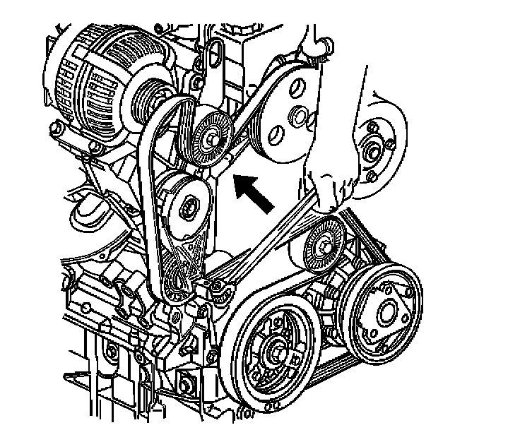
4. Release the drive belt tensioner.
Remove the drive belt from the compressor pulley.
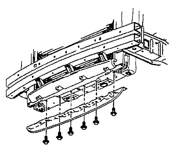
5. Remove the air baffle bolts.
6. Remove the air baffle.
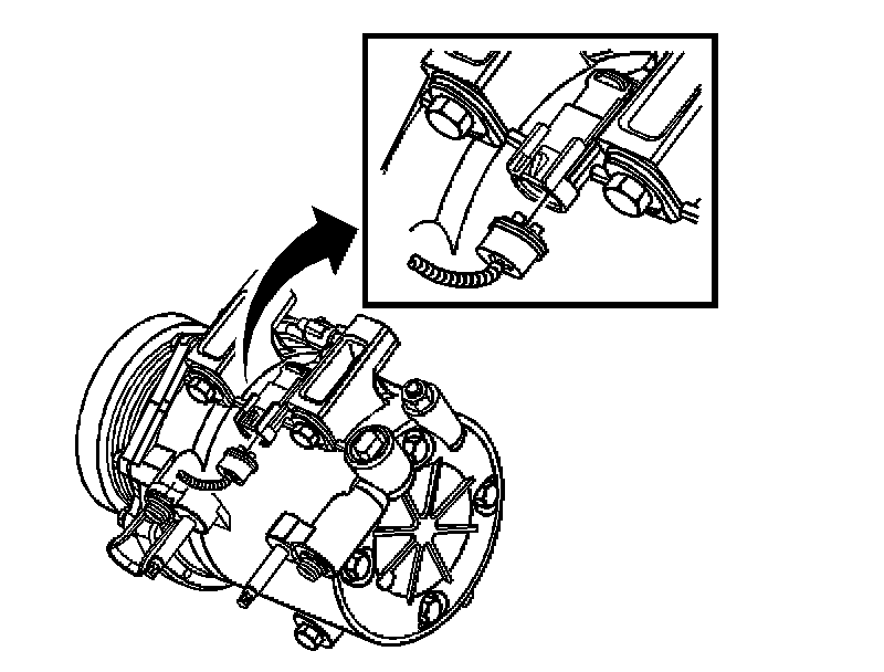
7. Disconnect the electrical connector from the compressor.
8. Disconnect the engine harness electrical connector.
Reposition the engine harness away from the compressor.
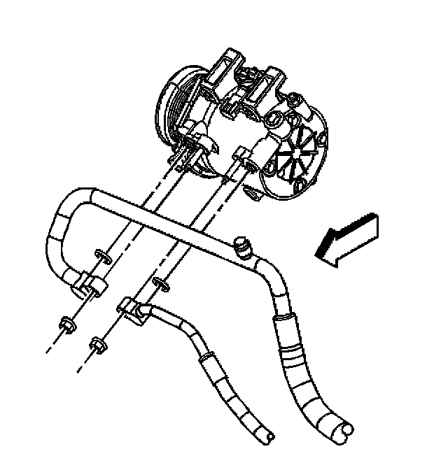
9. Remove the suction hose to compressor nut.
10. Disconnect the suction hose from the compressor.
IMPORTANT: Cap or tape the open A/C hoses immediately to prevent system contamination.
11. Remove the discharge hose to compressor nut.
12. Disconnect the discharge hose from the compressor.
13. Remove and discard the sealing washers.
14. Cap or tape off the suction hose.
15. Cap or tape off the discharge hose.
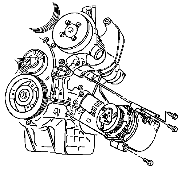
16. Remove compressor mounting bolts.
17. Remove the compressor.
18. If replacing the compressor, balance the compressor oil.
IMPORTANT: Replacement compressors are partially precharged with PAG oil.
INSTALLATION PROCEDURE
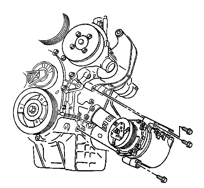
1. Install the compressor.
2. Install the compressor mounting bolts.
NOTE: Refer to Fastener Notice in Service Precautions.
Tighten
Tighten the bolts to 50 N.m (37 lb ft).
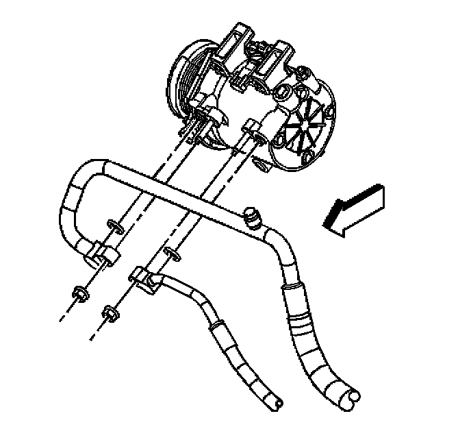
3. Remove cap or tape from the discharge hose.
4. Install a new sealing washer to the discharge hose.
5. Connect the discharge hose to the compressor.
6. Install the discharge hose to compressor nut.
Tighten
Tighten the nut to 16 N.m (12 lb ft).
7. Remove cap or tape from the suction hose.
8. Install a new sealing washer to the suction hose.
9. Connect the suction hose to the compressor.
10. Install the suction hose to compressor nut.
Tighten
Tighten the nut to 16 N.m (12 lb ft).
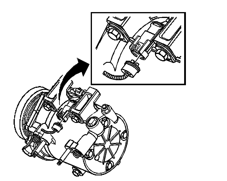
11. Connect the electrical connector to the compressor.
12. Connect the engine harness electrical connector.
13. Install the air baffle.
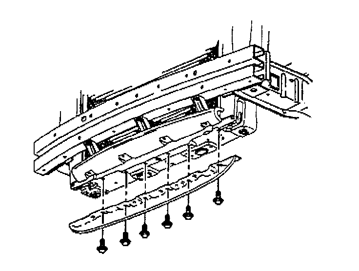
14. Install the air baffle bolts.
Tighten
Tighten the bolts to 20 N.m (15 lb ft).
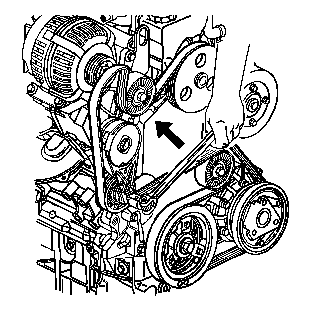
15. Release the drive belt tensioner.
Install the drive belt on to the compressor pulley.
16. Install the RH engine splash shield.
17. Lower the vehicle.
18. Evacuate and recharge the A/C system.
19. Leak test the fittings of the component using J 39400-A.
J 39400-A Halogen Leak Detector
REMOVAL PROCEDURE
1. Recover the refrigerant from the A/C system.
2. Raise and support the vehicle. Refer to Vehicle Lifting.
IMPORTANT: The A/C compressor is accessed through the right wheel opening. Turn the steering wheel to the right before lifting the vehicle.
3. Remove the RH engine splash shield.
4. Release the drive belt tensioner.
Remove the drive belt from the compressor pulley.
5. Remove the air baffle bolts.
6. Remove the air baffle.
7. Disconnect the electrical connector from the compressor.
8. Disconnect the engine harness electrical connector.
Reposition the engine harness away from the compressor.
9. Remove the suction hose to compressor nut.
10. Disconnect the suction hose from the compressor.
IMPORTANT: Cap or tape the open A/C hoses immediately to prevent system contamination.
11. Remove the discharge hose to compressor nut.
12. Disconnect the discharge hose from the compressor.
13. Remove and discard the sealing washers.
14. Cap or tape off the suction hose.
15. Cap or tape off the discharge hose.
16. Remove compressor mounting bolts.
17. Remove the compressor.
18. If replacing the compressor, balance the compressor oil.
IMPORTANT: Replacement compressors are partially precharged with PAG oil.
INSTALLATION PROCEDURE
1. Install the compressor.
2. Install the compressor mounting bolts.
NOTE: Refer to Fastener Notice in Service Precautions.
Tighten
Tighten the bolts to 50 N.m (37 lb ft).
3. Remove cap or tape from the discharge hose.
4. Install a new sealing washer to the discharge hose.
5. Connect the discharge hose to the compressor.
6. Install the discharge hose to compressor nut.
Tighten
Tighten the nut to 16 N.m (12 lb ft).
7. Remove cap or tape from the suction hose.
8. Install a new sealing washer to the suction hose.
9. Connect the suction hose to the compressor.
10. Install the suction hose to compressor nut.
Tighten
Tighten the nut to 16 N.m (12 lb ft).
11. Connect the electrical connector to the compressor.
12. Connect the engine harness electrical connector.
13. Install the air baffle.
14. Install the air baffle bolts.
Tighten
Tighten the bolts to 20 N.m (15 lb ft).
15. Release the drive belt tensioner.
Install the drive belt on to the compressor pulley.
16. Install the RH engine splash shield.
17. Lower the vehicle.
18. Evacuate and recharge the A/C system.
19. Leak test the fittings of the component using J 39400-A.
Factory Service Tools
Use the Manual With the Right Hardware
Pair factory procedures with proven DIY tools so the instructions are easier to execute.
Disclosure: Verified tool recommendations may earn an affiliate commission at no cost to you.
When to See a Mechanic
Stop DIY work and contact a certified mechanic immediately if any of the following apply:
- • You smell fuel, burning insulation, or see smoke.
- • Brakes feel soft, pull hard to one side, or make grinding noises.
- • The engine overheats, stalls repeatedly, or misfires under load.
- • You are missing required tools, torque specs, or safe lifting equipment.
- • You are not confident in the next step or safety outcome.