
Safety Warning
DIY auto repair can cause serious injury, fire, or vehicle damage. These guides are for informational purposes only. Always follow OEM torque specs, wear PPE, and consult a certified mechanic if you are unsure. You are solely responsible for your safety.
2002 Pontiac Aztek V6-3.4L VIN EFACTORY OEM SERVICE PROCEDURE
Subframe: Service and Repair
Frame Mount Replacement
^ Tools Required
- J 45677 Frame Mount Installer/Receiver, or equivalent
Removal Procedure
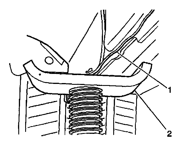
1. Using a wheel lift hoist, raise the vehicle. Refer to Vehicle Lifting.
2. Using utility stands (2), support some of the weight of the vehicle at the rear jacking points (1).
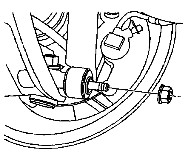
3. Remove the rear shock absorbers.
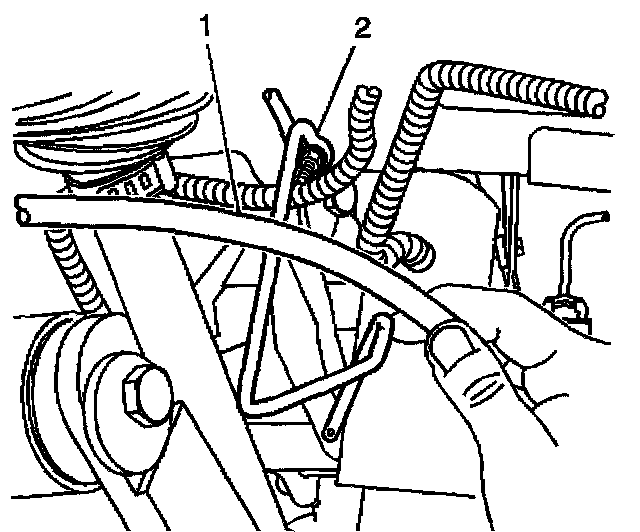
4. Remove the right hand brake cable (1) from the left guide loop (2).
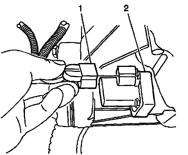
5. For AWD, disconnect the electrical connector (1) from the rear differential clutch pump check valve (2).
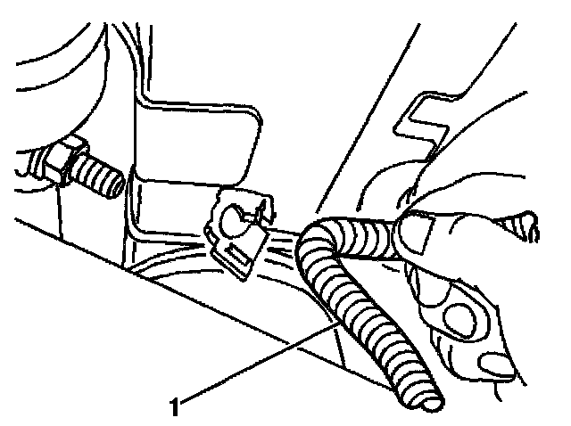
6. Remove both ABS wiring harnesses (1) from the frame rails.
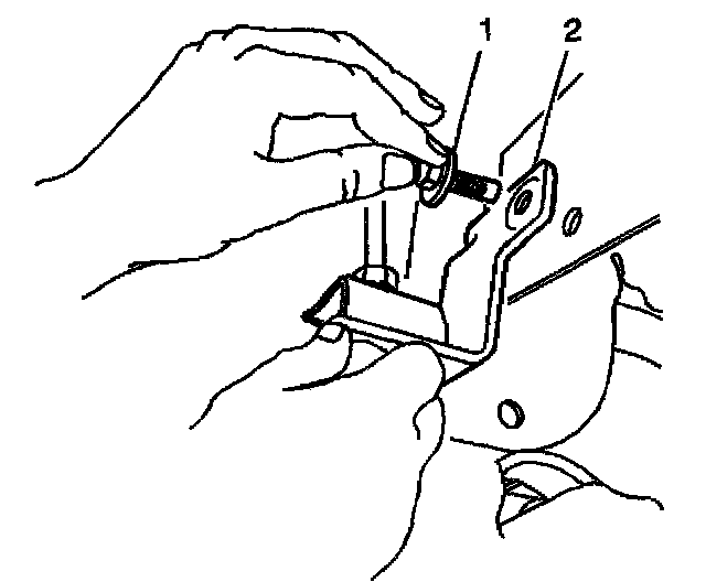
7. Remove the brake hose mounting bolts (1) from the body brackets (2).
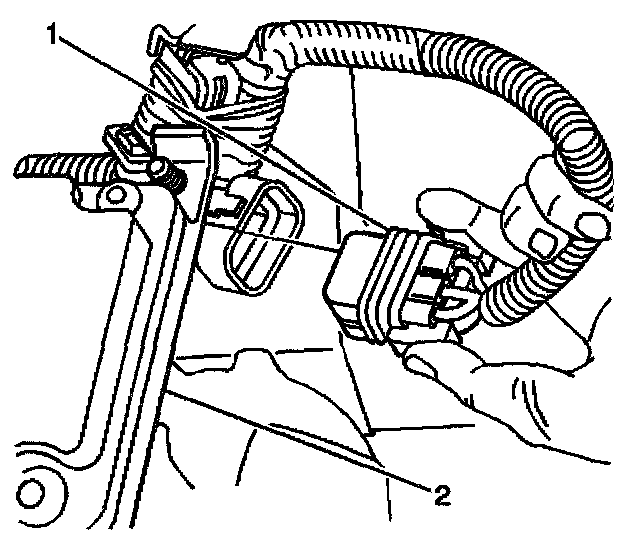
8. Remove the electrical connector (1) from the ALC height sensor (2).
9. Lower the rear wheel lift hoist to unload the suspension partially, letting the utility stands take some of the vehicle weight.
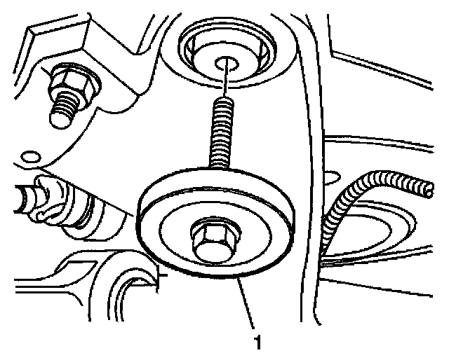
10. Remove the rear suspension module mounting bolts (1).
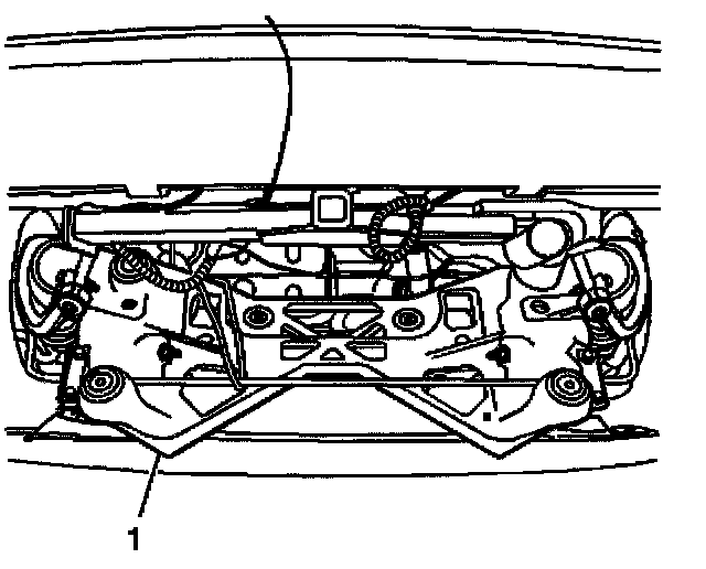
11. With the help from an assistant, lower and rotate back the rear suspension module (1), approximately 114 mm (4 1/2 inch) at the front mount, to install bushing removal/installation tool.
12. Remove the rear suspension module frame mounts using J 45677 or equivalent.
Installation Procedure
Important: Identify the orientation of the voids in the mounts and install the mounts with the voids fore and aft to the vehicle.
1. Install the new frame mounts using J 45677 or equivalent.
2. With the help from an assistant, guide the rear suspension module (1) into place while the assistant raises the hoist.
Notice: Refer to Fastener Notice in Service Precautions.
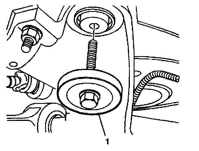
3. Install the rear suspension module mounting bolts (1).
^ Tighten the bolts to 125 Nm (92 ft. lbs.).
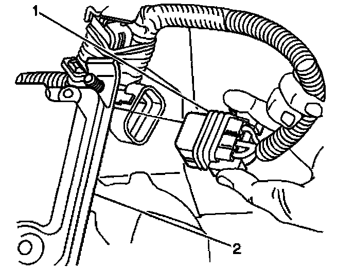
4. Connect the electrical connector (1) into the ALC height sensor (2).
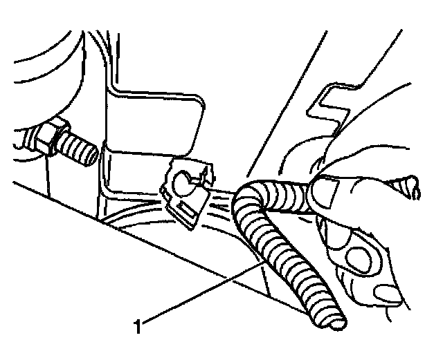
5. Install both ABS wiring harnesses (1) onto the frame rails.
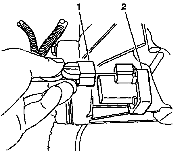
6. For AWD, connect the electrical connector (1) into the rear differential clutch pump check valve (2).
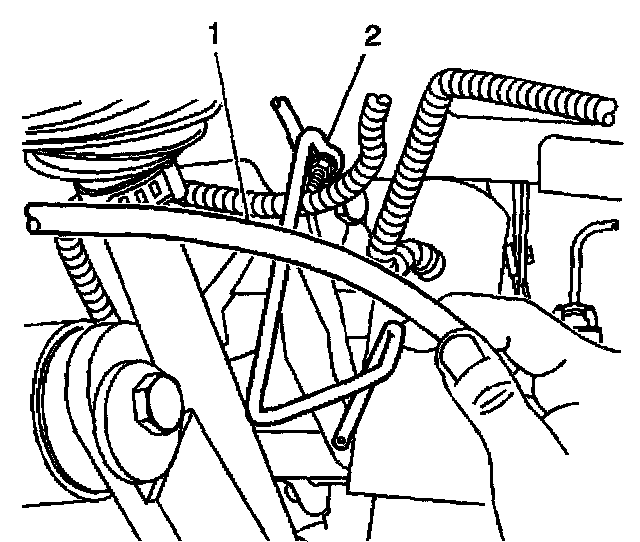
7. Install the right hand park brake cable (1) into the left guide loop (2).
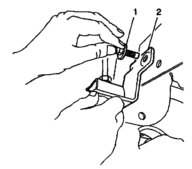
8. Install the brake hose mounting bolts (1) to the body brackets (2).
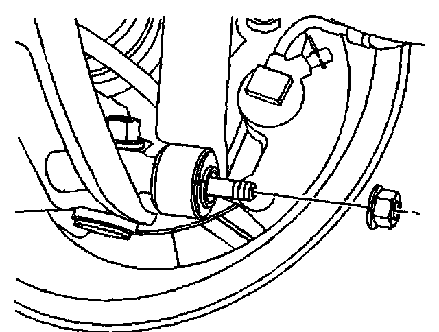
9. Install rear shock absorbers.
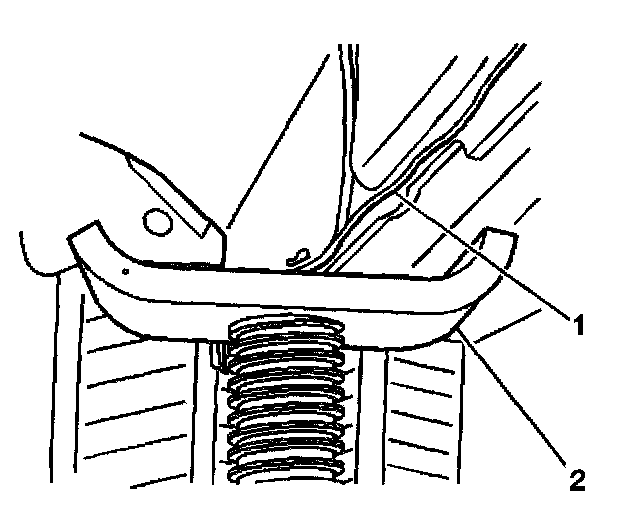
10. Remove the utility stands (2).
11. Lower the vehicle. Refer to Vehicle Lifting.
12. Check the rear suspension toe alignment and adjust if necessary to + 0.15 degrees to -0.15 degrees, individual toe.
^ Tools Required
- J 45677 Frame Mount Installer/Receiver, or equivalent
Removal Procedure
1. Using a wheel lift hoist, raise the vehicle. Refer to Vehicle Lifting.
2. Using utility stands (2), support some of the weight of the vehicle at the rear jacking points (1).
3. Remove the rear shock absorbers.
4. Remove the right hand brake cable (1) from the left guide loop (2).
5. For AWD, disconnect the electrical connector (1) from the rear differential clutch pump check valve (2).
6. Remove both ABS wiring harnesses (1) from the frame rails.
7. Remove the brake hose mounting bolts (1) from the body brackets (2).
8. Remove the electrical connector (1) from the ALC height sensor (2).
9. Lower the rear wheel lift hoist to unload the suspension partially, letting the utility stands take some of the vehicle weight.
10. Remove the rear suspension module mounting bolts (1).
11. With the help from an assistant, lower and rotate back the rear suspension module (1), approximately 114 mm (4 1/2 inch) at the front mount, to install bushing removal/installation tool.
12. Remove the rear suspension module frame mounts using J 45677 or equivalent.
Installation Procedure
Important: Identify the orientation of the voids in the mounts and install the mounts with the voids fore and aft to the vehicle.
1. Install the new frame mounts using J 45677 or equivalent.
2. With the help from an assistant, guide the rear suspension module (1) into place while the assistant raises the hoist.
Notice: Refer to Fastener Notice in Service Precautions.
3. Install the rear suspension module mounting bolts (1).
^ Tighten the bolts to 125 Nm (92 ft. lbs.).
4. Connect the electrical connector (1) into the ALC height sensor (2).
5. Install both ABS wiring harnesses (1) onto the frame rails.
6. For AWD, connect the electrical connector (1) into the rear differential clutch pump check valve (2).
7. Install the right hand park brake cable (1) into the left guide loop (2).
8. Install the brake hose mounting bolts (1) to the body brackets (2).
9. Install rear shock absorbers.
10. Remove the utility stands (2).
11. Lower the vehicle. Refer to Vehicle Lifting.
12. Check the rear suspension toe alignment and adjust if necessary to + 0.15 degrees to -0.15 degrees, individual toe.
Factory Service Tools
Use the Manual With the Right Hardware
Pair factory procedures with proven DIY tools so the instructions are easier to execute.
Disclosure: Verified tool recommendations may earn an affiliate commission at no cost to you.
When to See a Mechanic
Stop DIY work and contact a certified mechanic immediately if any of the following apply:
- • You smell fuel, burning insulation, or see smoke.
- • Brakes feel soft, pull hard to one side, or make grinding noises.
- • The engine overheats, stalls repeatedly, or misfires under load.
- • You are missing required tools, torque specs, or safe lifting equipment.
- • You are not confident in the next step or safety outcome.