
Safety Warning
DIY auto repair can cause serious injury, fire, or vehicle damage. These guides are for informational purposes only. Always follow OEM torque specs, wear PPE, and consult a certified mechanic if you are unsure. You are solely responsible for your safety.
2000 Pontiac Firefly (CANADA) L4-1.3LFACTORY OEM SERVICE PROCEDURE
Distributor Replacement
REMOVAL PROCEDURE
CAUTION: Refer to Battery Disconnect Caution in Service Precautions.
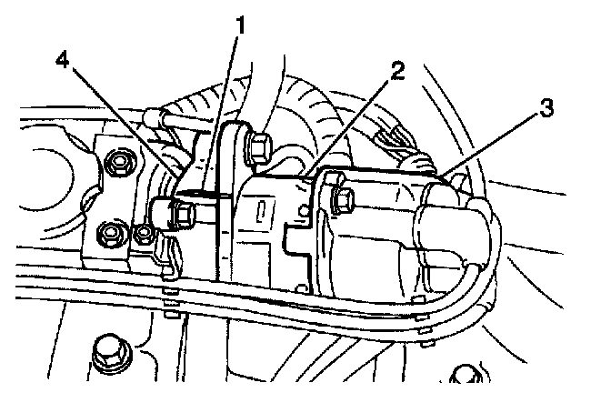
1. Disconnect the negative (-) battery cable.
2. Disconnect the distributor electrical connector.
3. Remove two screws and the distributor cap from the distributor.
4. Mark the distributor housing (1) position on the cylinder head (4).
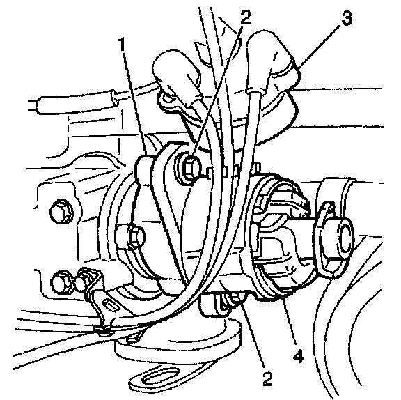
5. Remove two distributor flange bolts (2) and the distributor housing (4) from the cylinder head.
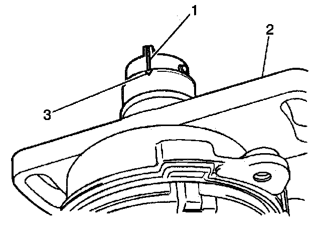
6. Mark the distributor coupling position (1) on the distributor housing (2).
7. Inspect the distributor cap and the rotor for cracks, terminal corrosion and wear. Replace as necessary.
IF DISTRIBUTOR POSITION WAS LOST
TOOL REQUIRED
J 22794 Spark Plug Port Adaptor
If the engine was accidently cranked after the distributor was removed, the following procedure can be used to properly position the distributor.
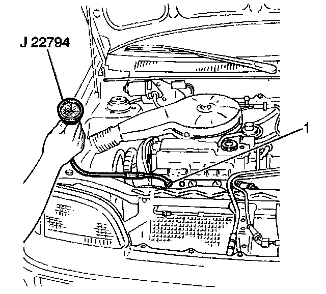
1. Crank the engine until the number 1 cylinder is at Top Dead Center (TDC) on the compression stroke. This can be accomplished by the following:
1.1. Remove the FI fuse from the fuse and relay box.
1.2. Remove the number 1 spark plug.
1.3. Install a J 22794 spark plug port adaptor and a compression gauge into the spark plug cavity.
1.4. Crank the engine and observe the compression gauge. The TDC of the cylinder's compression stroke occurs when the compression reading is the highest.
2. Align the timing mark on the crankshaft pulley to the zero (0) position on the timing indicator.
3. Position the rotor to the number 1 cylinder position.
4. Install the distributor.
5. Remove the J 22794 spark plug port adaptor and the compression gauge.
6. Install the number 1 spark plug.
NOTE: Refer to Fastener Notice in Service Precautions.
Tighten
Tighten the spark plug to 28 N.m (21 lb ft).
7. Install the FI fuse into the fuse and relay box.
8. Set the ignition timing. Refer to Ignition Timing Adjustment.
INSTALLATION PROCEDURE
1. Match the distributor coupling-to-distributor housing alignment marks (1,3).
2. Install the distributor housing to the cylinder head. Match the marks (1) made on the cylinder head and the distributor housing during removal.
3. Install two distributor flange bolts (2). Do not tighten fully.
4. Install the new distributor cap seal to the distributor cap.
5. Install the distributor cap to the distributor. Secure the cap with two screws.
6. Connect the distributor electrical connector.
NOTE: Refer to Fastener Notice in Service Precautions.
7. Connect the negative (-) battery cable.
Tighten
Tighten the negative (-) battery cable-to-negative (-) battery terminal retainer to 15 N.m (11 lb ft).
8. Set the ignition timing on the 1.0L only. Refer to Ignition Timing Adjustment in Engine Controls.
CAUTION: Refer to Battery Disconnect Caution in Service Precautions.
1. Disconnect the negative (-) battery cable.
2. Disconnect the distributor electrical connector.
3. Remove two screws and the distributor cap from the distributor.
4. Mark the distributor housing (1) position on the cylinder head (4).
5. Remove two distributor flange bolts (2) and the distributor housing (4) from the cylinder head.
6. Mark the distributor coupling position (1) on the distributor housing (2).
7. Inspect the distributor cap and the rotor for cracks, terminal corrosion and wear. Replace as necessary.
IF DISTRIBUTOR POSITION WAS LOST
TOOL REQUIRED
J 22794 Spark Plug Port Adaptor
If the engine was accidently cranked after the distributor was removed, the following procedure can be used to properly position the distributor.
1. Crank the engine until the number 1 cylinder is at Top Dead Center (TDC) on the compression stroke. This can be accomplished by the following:
1.1. Remove the FI fuse from the fuse and relay box.
1.2. Remove the number 1 spark plug.
1.3. Install a J 22794 spark plug port adaptor and a compression gauge into the spark plug cavity.
1.4. Crank the engine and observe the compression gauge. The TDC of the cylinder's compression stroke occurs when the compression reading is the highest.
2. Align the timing mark on the crankshaft pulley to the zero (0) position on the timing indicator.
3. Position the rotor to the number 1 cylinder position.
4. Install the distributor.
5. Remove the J 22794 spark plug port adaptor and the compression gauge.
6. Install the number 1 spark plug.
NOTE: Refer to Fastener Notice in Service Precautions.
Tighten
Tighten the spark plug to 28 N.m (21 lb ft).
7. Install the FI fuse into the fuse and relay box.
8. Set the ignition timing. Refer to Ignition Timing Adjustment.
INSTALLATION PROCEDURE
1. Match the distributor coupling-to-distributor housing alignment marks (1,3).
2. Install the distributor housing to the cylinder head. Match the marks (1) made on the cylinder head and the distributor housing during removal.
3. Install two distributor flange bolts (2). Do not tighten fully.
4. Install the new distributor cap seal to the distributor cap.
5. Install the distributor cap to the distributor. Secure the cap with two screws.
6. Connect the distributor electrical connector.
NOTE: Refer to Fastener Notice in Service Precautions.
7. Connect the negative (-) battery cable.
Tighten
Tighten the negative (-) battery cable-to-negative (-) battery terminal retainer to 15 N.m (11 lb ft).
8. Set the ignition timing on the 1.0L only. Refer to Ignition Timing Adjustment in Engine Controls.
Factory Service Tools
Use the Manual With the Right Hardware
Pair factory procedures with proven DIY tools so the instructions are easier to execute.
Disclosure: Verified tool recommendations may earn an affiliate commission at no cost to you.
When to See a Mechanic
Stop DIY work and contact a certified mechanic immediately if any of the following apply:
- • You smell fuel, burning insulation, or see smoke.
- • Brakes feel soft, pull hard to one side, or make grinding noises.
- • The engine overheats, stalls repeatedly, or misfires under load.
- • You are missing required tools, torque specs, or safe lifting equipment.
- • You are not confident in the next step or safety outcome.