
Safety Warning
DIY auto repair can cause serious injury, fire, or vehicle damage. These guides are for informational purposes only. Always follow OEM torque specs, wear PPE, and consult a certified mechanic if you are unsure. You are solely responsible for your safety.
1998 Oldsmobile Aurora V8-4.0L VIN CFACTORY OEM SERVICE PROCEDURE
Intake Manifold Removal

1. Remove the intake manifold sight shield. Refer to Engine Cover Replacement
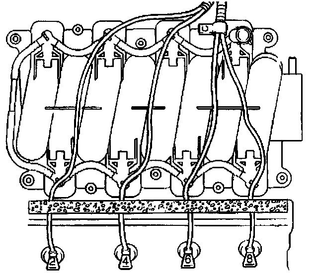
2. Disconnect the spark plug wires from the left bank spark plugs and the molded retainers in the intake manifold. Lay the wires aside.
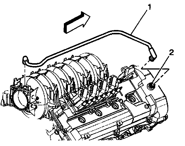
3. Disconnect the PCV valve (2) and both feed tubes (1) from the camshaft covers.
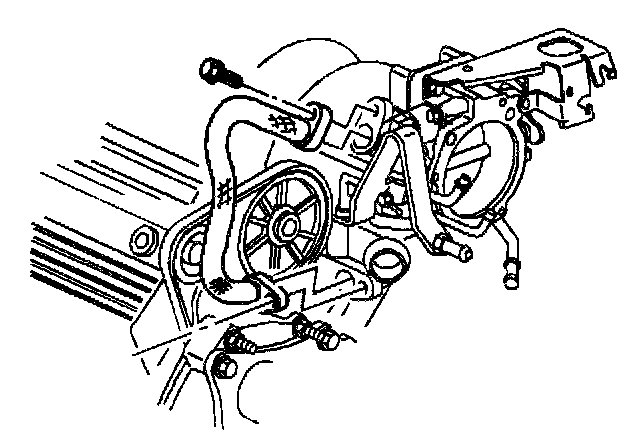
4. Disconnect the EGR and crankcase ventilation pipe at the throttle body spacer.
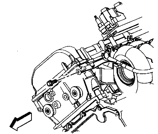
5. Disconnect the fuel rail ground wire at the rear cylinder head.
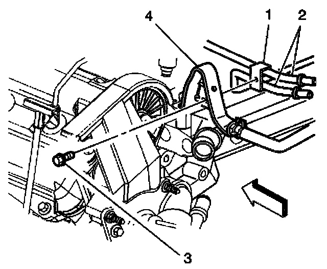
6. Remove the fuel rail bracket retaining bolt (3) at the rear lift bracket (4).
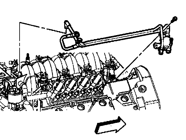
7. Remove the purge solenoid harness by removing the retaining bolt and disconnecting from the intake manifold.
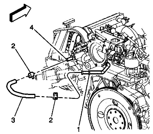
8. Disconnect the throttle body coolant hose (3) from the water crossover fitting (4).
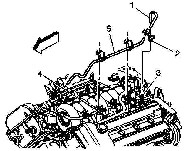
9. Disconnect the throttle body coolant outlet hose (1) from the throttle body (8) and remove the coolant overflow pipe (5) from the intake manifold studs (4).
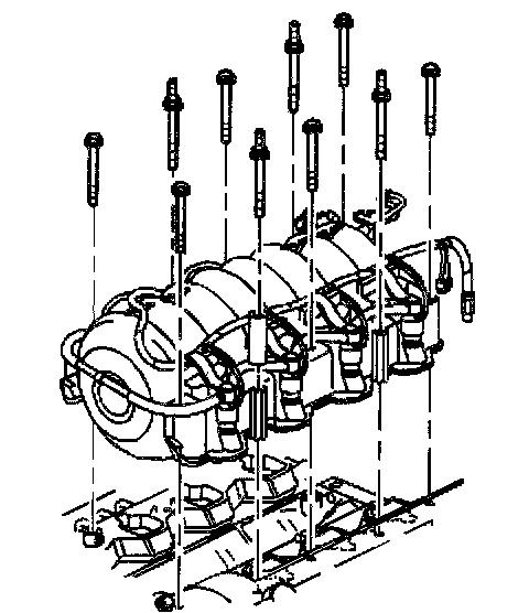
10. Loosen and remove the intake manifold bolts.
11. Remove the intake manifold assembly.
IMPORTANT: The intake manifold carrier gaskets are attached to the intake manifold through a snap-lock feature. When you remove the intake manifold, the carrier gaskets will remain attached to the manifold. It is not necessary to replace the gaskets unless there is damage to the seals.
IMPORTANT: The following steps are only necessary if the throttle body or intake manifold require replacement.
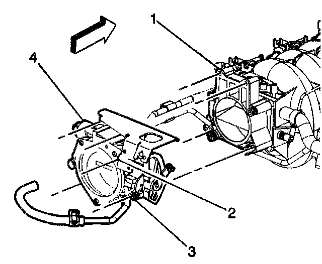
12. Remove the four throttle body (4) to spacer (1) retaining bolts (3).
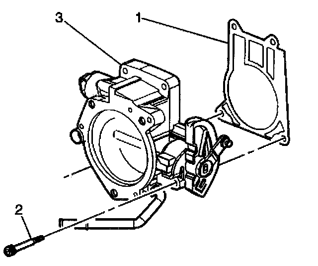
13. Remove the throttle body gasket (1) and discard. Make sure all gasket material is removed.
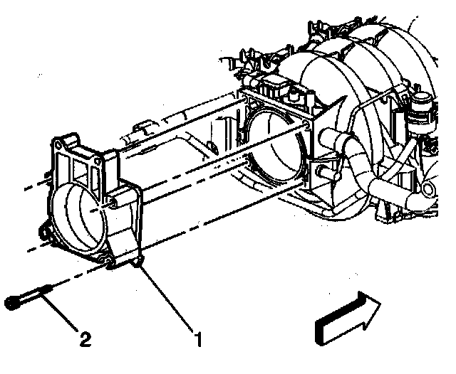
14. Remove the throttle body spacer retaining, bolts (2) and throttle body spacer (1) from the intake manifold.
15. Remove the MAP sensor from the top of the spacer mounting location.
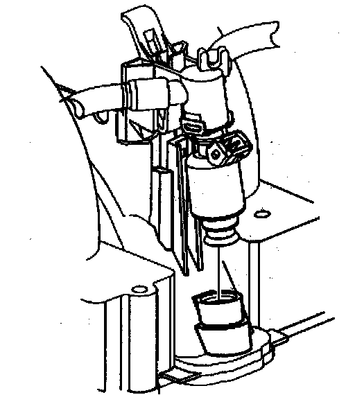
16. Disconnect the eight fuel rail snap lock retainers by squeezing the tab and lifting the fuel rail simultaneously.
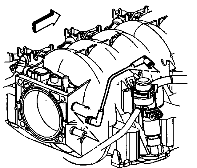
17. Disconnect the fuel regulator vacuum tube.
18. Remove the brake booster vacuum hose.
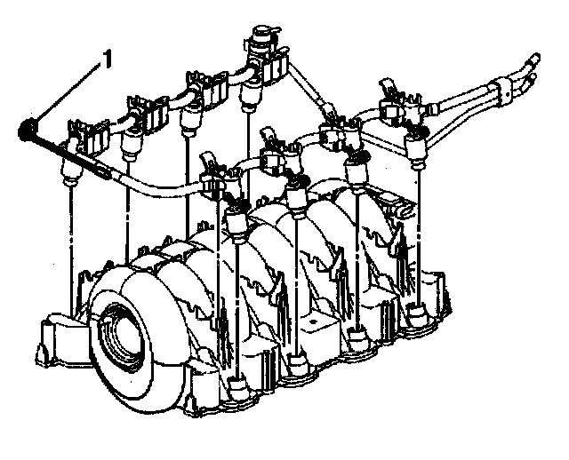
19. Lift the entire fuel rail and injector assembly from the intake manifold when all eight snap lock retainers are released. Note the location of the fuel rail ground strap (1).
Factory Service Tools
Use the Manual With the Right Hardware
Pair factory procedures with proven DIY tools so the instructions are easier to execute.
Disclosure: Verified tool recommendations may earn an affiliate commission at no cost to you.
When to See a Mechanic
Stop DIY work and contact a certified mechanic immediately if any of the following apply:
- • You smell fuel, burning insulation, or see smoke.
- • Brakes feel soft, pull hard to one side, or make grinding noises.
- • The engine overheats, stalls repeatedly, or misfires under load.
- • You are missing required tools, torque specs, or safe lifting equipment.
- • You are not confident in the next step or safety outcome.
Rather have a pro handle this?
A certified mobile mechanic comes to your home or office. They bring the tools, you stay comfortable. No tow truck, no waiting room, no surprises.
Comes to youSame-day available12-month warranty
Get a Free QuoteNo obligation. See pricing before you book.