
Safety Warning
DIY auto repair can cause serious injury, fire, or vehicle damage. These guides are for informational purposes only. Always follow OEM torque specs, wear PPE, and consult a certified mechanic if you are unsure. You are solely responsible for your safety.
2008 Mitsubishi Eclipse L4-2.4L (4G69)FACTORY OEM SERVICE PROCEDURE
Ignition Control Module: Testing and Inspection
IGNITION COIL AND IGNITION POWER TRANSISTOR
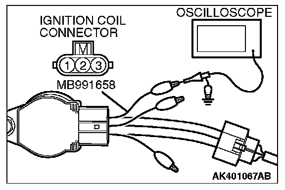
Required Special Tools:
- MB991658: Test Harness
- MB991923: Power Plant ECU Check Harness
Measurement Method
1. Disconnect the ignition coil connector, and connect the test harness special tool (MB991658) between the separated connector.
2. Connect the oscilloscope probe to ignition coil connector terminal No. 3.
Alternate method
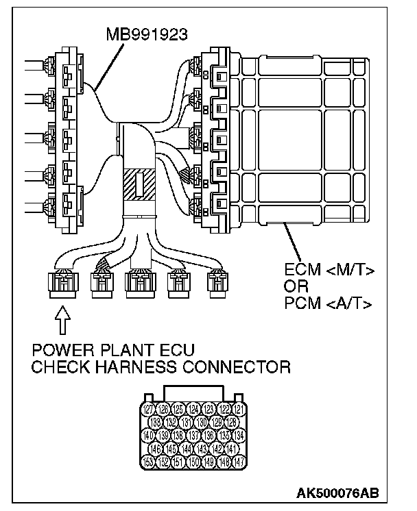
1. Disconnect all ECM [M/T] connectors or PCM [A/T] connectors. Connect the check harness special tool (MB991923) between the separated connectors.
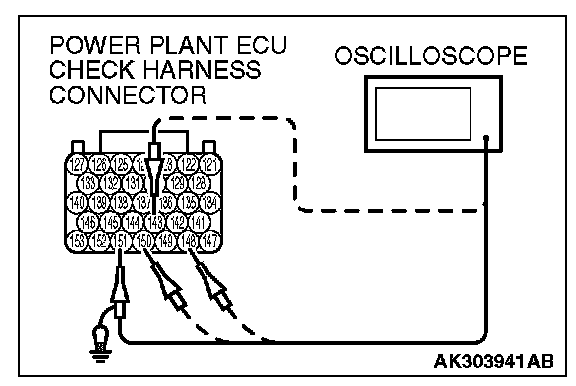
2. Connect the oscilloscope probe to each check harness connector terminal to analyze each cylinder:
- Terminal No. 151 for the number 1 cylinder.
- Terminal No. 143 for the number 2 cylinder.
- Terminal No. 150 for the number 3 cylinder.
- Terminal No. 148 for the number 4 cylinder.
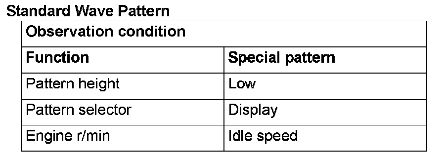
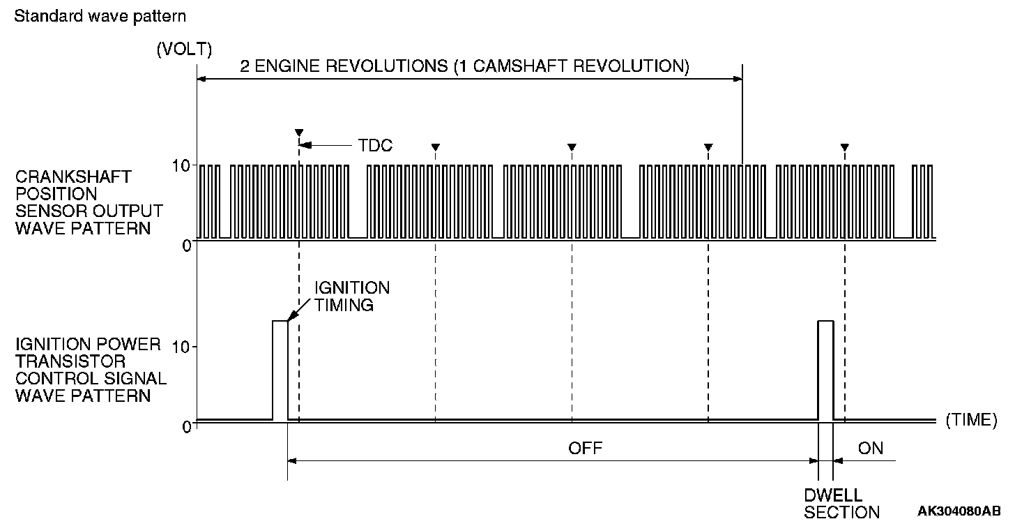
Wave Pattern Observation Points
Point: The power transistor control signal (ignition timing) is advanced when the engine speed is increased.
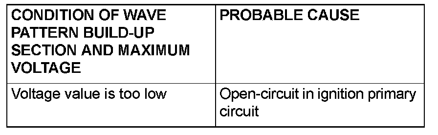
Examples of Abnormal Wave Patterns
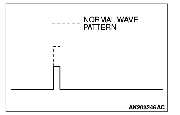
Example 1 (Wave pattern during engine cranking)
- Cause of problem
Open-circuit in ignition primary circuit
- Wave pattern characteristics
Voltage value is too low.
Required Special Tools:
- MB991658: Test Harness
- MB991923: Power Plant ECU Check Harness
Measurement Method
1. Disconnect the ignition coil connector, and connect the test harness special tool (MB991658) between the separated connector.
2. Connect the oscilloscope probe to ignition coil connector terminal No. 3.
Alternate method
1. Disconnect all ECM [M/T] connectors or PCM [A/T] connectors. Connect the check harness special tool (MB991923) between the separated connectors.
2. Connect the oscilloscope probe to each check harness connector terminal to analyze each cylinder:
- Terminal No. 151 for the number 1 cylinder.
- Terminal No. 143 for the number 2 cylinder.
- Terminal No. 150 for the number 3 cylinder.
- Terminal No. 148 for the number 4 cylinder.
Standard Wave Pattern:
Standard Wave Pattern:
Wave Pattern Observation Points
Point: The power transistor control signal (ignition timing) is advanced when the engine speed is increased.
Examples of Abnormal Wave Patterns
Example 1 (Wave pattern during engine cranking)
- Cause of problem
Open-circuit in ignition primary circuit
- Wave pattern characteristics
Voltage value is too low.
Factory Service Tools
Use the Manual With the Right Hardware
Pair factory procedures with proven DIY tools so the instructions are easier to execute.
Disclosure: Verified tool recommendations may earn an affiliate commission at no cost to you.
When to See a Mechanic
Stop DIY work and contact a certified mechanic immediately if any of the following apply:
- • You smell fuel, burning insulation, or see smoke.
- • Brakes feel soft, pull hard to one side, or make grinding noises.
- • The engine overheats, stalls repeatedly, or misfires under load.
- • You are missing required tools, torque specs, or safe lifting equipment.
- • You are not confident in the next step or safety outcome.
Rather have a pro handle this?
A certified mobile mechanic comes to your home or office. They bring the tools, you stay comfortable. No tow truck, no waiting room, no surprises.
Comes to youSame-day available12-month warranty
Get a Free QuoteNo obligation. See pricing before you book.