
Safety Warning
DIY auto repair can cause serious injury, fire, or vehicle damage. These guides are for informational purposes only. Always follow OEM torque specs, wear PPE, and consult a certified mechanic if you are unsure. You are solely responsible for your safety.
2008 Mitsubishi Eclipse L4-2.4L (4G69)FACTORY OEM SERVICE PROCEDURE
Inspection Procedure 7
INSPECTION PROCEDURE 7: Hard Starting
COMMENT
- In cases such as the above, the cause is usually either weak spark, improper air/fuel mixture or low compression.
TROUBLESHOOTING HINTS (The most likely causes for this case:)
- Malfunction of the ignition system.
- Malfunction of the injector system.
- Poor fuel quality. (Contamination)
- Poor compression.
DIAGNOSIS
Required Special Tools:
- MB991958: Scan Tool (M.U.T.-III Sub Assembly)
- MB991824: V.C.I.
- MB991827: USB Cable
- MB991910: Main Harness A
STEP 1. Measure the battery positive voltage.
1. Measure the battery positive voltage during cranking.
- The voltage should remain greater than 8 volts while the engine is cranked.
Q: Does the voltage remain greater than 8 volts while the engine is cranked?
YES : Go to Step 2.
NO : Refer to chassis electrical, Battery-Battery check.
STEP 2. Using scan tool MB991958, read the diagnostic trouble code (DTC).
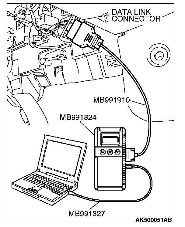
CAUTION: To prevent damage to scan tool MB991958, always turn the ignition switch to the "LOCK" (OFF) position before connecting or disconnecting scan tool MB991958.
1. Connect scan tool MB991958 to the data link connector.
2. Turn the ignition switch to the "ON" position.
3. Read the DTC.
4. Turn the ignition switch to the "LOCK" (OFF) position.
Q: Is the DTC set?
YES : Refer to MFI, Diagnostic Trouble Code Chart. Diagnostic Trouble Code Descriptions
NO : Go to Step 3.
STEP 3. Using scan tool MB991958, check actuator test.
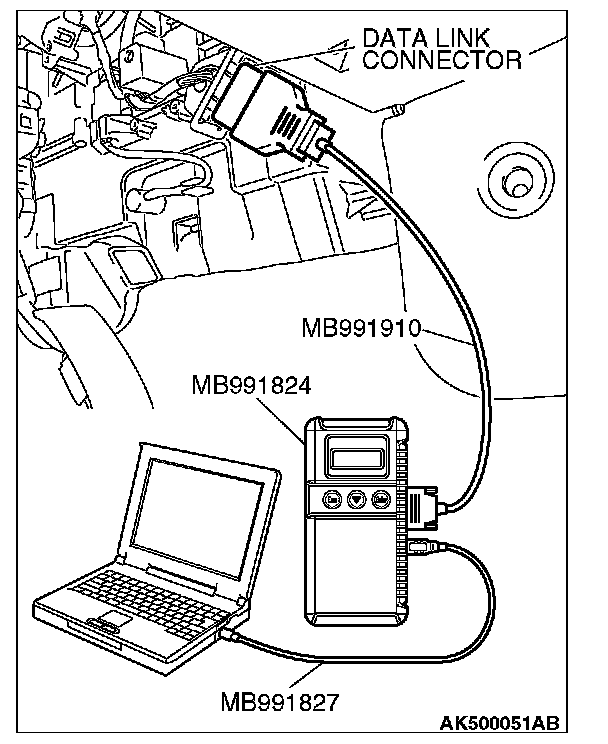
1. Turn the ignition switch to the "ON" position.
2. Check the following item in the actuator test. Refer to MFI, Actuator Test Reference Table. Actuator Test Reference Table
a. Item 9: Fuel Pump.
3. Turn the ignition switch to the "LOCK" (OFF) position.
Q: Is the actuator operating properly?
YES : Go to Step 4.
NO : Repair or Replace it. Then confirm that the malfunction symptom is eliminated.
STEP 4. Using scan tool MB991958, check data list.
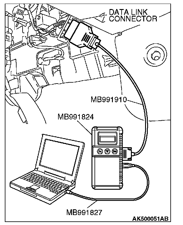
1. Turn the ignition switch to the "ON" position.
2. Check the following item in the data list. Refer to MFI, Data List Reference Table. Datal List Reference Table
a. Item 6: Engine Coolant Temperature Sensor.
3. Turn the ignition switch to the "LOCK" (OFF) position.
Q: Is the sensor operating properly?
YES : Go to Step 5.
NO : Repair or Replace it. Then confirm that the malfunction symptom is eliminated.
STEP 5. Check the ignition timing.
1. Check the ignition timing at cranking.
Standard value: 5° BTDC ± 3°
Q: Is the ignition timing normal?
YES : Go to Step 6.
NO : Check that the crankshaft position sensor and timing belt cover are in the correct position. Then confirm that the malfunction symptom is eliminated.
STEP 6. Check harness connector B-01 or B-03 or B-26 or B-29 at injector for damage.
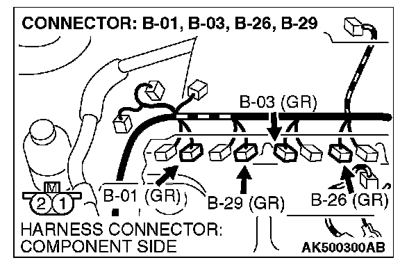
Q: Is the harness connector in good condition?
YES : Go to Step 7.
NO : Repair or replace it. Refer to general (electrical), Harness Connector Inspection. Then confirm that the malfunction symptom is eliminated.
STEP 7. Check the injector.
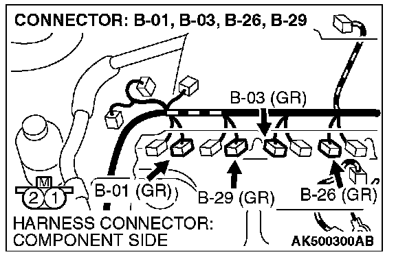
1. Disconnect the injector connector B-01, B-03, B-26 and B-29.
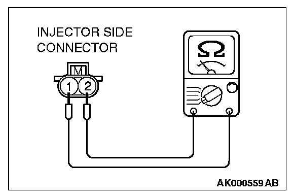
2. Measure the resistance between each injector side connector terminal No. 1 and No. 2.
Standard value: 10.5 - 13.5 ohms [at 20 °C (68 °F)]
Q: Is the measured resistance between 10.5 and 13.5 ohms [at 20 °C (68 °F)]?
YES : Go to Step 8.
NO : Repair the injector. Then confirm that the malfunction symptom is eliminated.
STEP 8. Check harness connector B-22 at ECM [M/T] or PCM [A/T] for damage.
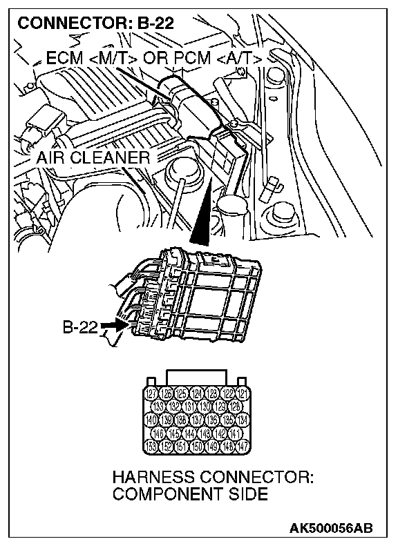
Q: Is the harness connector in good condition?
YES : Go to Step 9.
NO : Repair or replace it. Refer to general (electrical), Harness Connector Inspection. Then confirm that the malfunction symptom is eliminated.
STEP 9. Check for harness damage between injector connector and ECM [M/T] or PCM [A/T] connector.
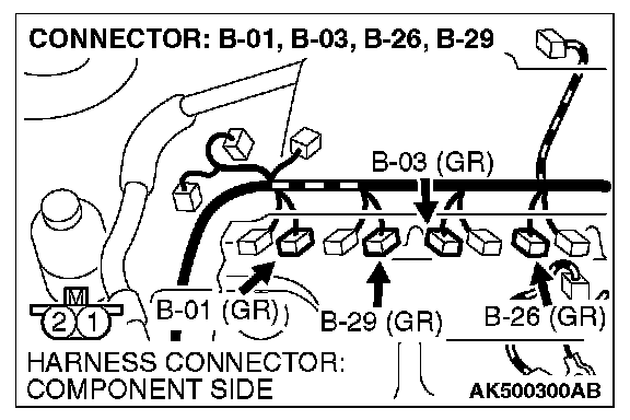
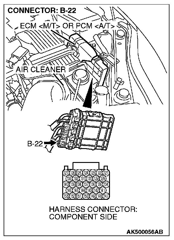
a. Check the harness wire between injector connector B-01 (terminal No. 2) and ECM [M/T] or PCM [A/T] connector B-22 (terminal No. 153) at No. 1 cylinder.
b. Check the harness wire between injector connector B-29 (terminal No. 2) and ECM [M/T] or PCM [A/T] connector B-22 (terminal No. 146) at No. 2 cylinder.
c. Check the harness wire between injector connector B-03 (terminal No. 2) and ECM [M/T] or PCM [A/T] connector B-22 (terminal No. 140) at No. 3 cylinder.
d. Check the harness wire between injector connector B-26 (terminal No. 2) and ECM [M/T] or PCM [A/T] connector B-22 (terminal No. 139) at No. 4 cylinder.
Q: Is the harness wire in good condition?
YES : Check the following items, and repair or replace the defective items.
a. Check the ignition coil and spark plugs.
b. Check if the injectors are clogged.
c. Check compression pressure.
d. Check if the foreign materials (water, kerosene, etc.) got into fuel.
Then confirm that the malfunction symptom is eliminated.
NO : Repair it. Then confirm that the malfunction symptom is eliminated.
COMMENT
- In cases such as the above, the cause is usually either weak spark, improper air/fuel mixture or low compression.
TROUBLESHOOTING HINTS (The most likely causes for this case:)
- Malfunction of the ignition system.
- Malfunction of the injector system.
- Poor fuel quality. (Contamination)
- Poor compression.
DIAGNOSIS
Required Special Tools:
- MB991958: Scan Tool (M.U.T.-III Sub Assembly)
- MB991824: V.C.I.
- MB991827: USB Cable
- MB991910: Main Harness A
STEP 1. Measure the battery positive voltage.
1. Measure the battery positive voltage during cranking.
- The voltage should remain greater than 8 volts while the engine is cranked.
Q: Does the voltage remain greater than 8 volts while the engine is cranked?
YES : Go to Step 2.
NO : Refer to chassis electrical, Battery-Battery check.
STEP 2. Using scan tool MB991958, read the diagnostic trouble code (DTC).
CAUTION: To prevent damage to scan tool MB991958, always turn the ignition switch to the "LOCK" (OFF) position before connecting or disconnecting scan tool MB991958.
1. Connect scan tool MB991958 to the data link connector.
2. Turn the ignition switch to the "ON" position.
3. Read the DTC.
4. Turn the ignition switch to the "LOCK" (OFF) position.
Q: Is the DTC set?
YES : Refer to MFI, Diagnostic Trouble Code Chart. Diagnostic Trouble Code Descriptions
NO : Go to Step 3.
STEP 3. Using scan tool MB991958, check actuator test.
1. Turn the ignition switch to the "ON" position.
2. Check the following item in the actuator test. Refer to MFI, Actuator Test Reference Table. Actuator Test Reference Table
a. Item 9: Fuel Pump.
3. Turn the ignition switch to the "LOCK" (OFF) position.
Q: Is the actuator operating properly?
YES : Go to Step 4.
NO : Repair or Replace it. Then confirm that the malfunction symptom is eliminated.
STEP 4. Using scan tool MB991958, check data list.
1. Turn the ignition switch to the "ON" position.
2. Check the following item in the data list. Refer to MFI, Data List Reference Table. Datal List Reference Table
a. Item 6: Engine Coolant Temperature Sensor.
3. Turn the ignition switch to the "LOCK" (OFF) position.
Q: Is the sensor operating properly?
YES : Go to Step 5.
NO : Repair or Replace it. Then confirm that the malfunction symptom is eliminated.
STEP 5. Check the ignition timing.
1. Check the ignition timing at cranking.
Standard value: 5° BTDC ± 3°
Q: Is the ignition timing normal?
YES : Go to Step 6.
NO : Check that the crankshaft position sensor and timing belt cover are in the correct position. Then confirm that the malfunction symptom is eliminated.
STEP 6. Check harness connector B-01 or B-03 or B-26 or B-29 at injector for damage.
Q: Is the harness connector in good condition?
YES : Go to Step 7.
NO : Repair or replace it. Refer to general (electrical), Harness Connector Inspection. Then confirm that the malfunction symptom is eliminated.
STEP 7. Check the injector.
1. Disconnect the injector connector B-01, B-03, B-26 and B-29.
2. Measure the resistance between each injector side connector terminal No. 1 and No. 2.
Standard value: 10.5 - 13.5 ohms [at 20 °C (68 °F)]
Q: Is the measured resistance between 10.5 and 13.5 ohms [at 20 °C (68 °F)]?
YES : Go to Step 8.
NO : Repair the injector. Then confirm that the malfunction symptom is eliminated.
STEP 8. Check harness connector B-22 at ECM [M/T] or PCM [A/T] for damage.
Q: Is the harness connector in good condition?
YES : Go to Step 9.
NO : Repair or replace it. Refer to general (electrical), Harness Connector Inspection. Then confirm that the malfunction symptom is eliminated.
STEP 9. Check for harness damage between injector connector and ECM [M/T] or PCM [A/T] connector.
a. Check the harness wire between injector connector B-01 (terminal No. 2) and ECM [M/T] or PCM [A/T] connector B-22 (terminal No. 153) at No. 1 cylinder.
b. Check the harness wire between injector connector B-29 (terminal No. 2) and ECM [M/T] or PCM [A/T] connector B-22 (terminal No. 146) at No. 2 cylinder.
c. Check the harness wire between injector connector B-03 (terminal No. 2) and ECM [M/T] or PCM [A/T] connector B-22 (terminal No. 140) at No. 3 cylinder.
d. Check the harness wire between injector connector B-26 (terminal No. 2) and ECM [M/T] or PCM [A/T] connector B-22 (terminal No. 139) at No. 4 cylinder.
Q: Is the harness wire in good condition?
YES : Check the following items, and repair or replace the defective items.
a. Check the ignition coil and spark plugs.
b. Check if the injectors are clogged.
c. Check compression pressure.
d. Check if the foreign materials (water, kerosene, etc.) got into fuel.
Then confirm that the malfunction symptom is eliminated.
NO : Repair it. Then confirm that the malfunction symptom is eliminated.
Factory Service Tools
Use the Manual With the Right Hardware
Pair factory procedures with proven DIY tools so the instructions are easier to execute.
Disclosure: Verified tool recommendations may earn an affiliate commission at no cost to you.
When to See a Mechanic
Stop DIY work and contact a certified mechanic immediately if any of the following apply:
- • You smell fuel, burning insulation, or see smoke.
- • Brakes feel soft, pull hard to one side, or make grinding noises.
- • The engine overheats, stalls repeatedly, or misfires under load.
- • You are missing required tools, torque specs, or safe lifting equipment.
- • You are not confident in the next step or safety outcome.
Rather have a pro handle this?
A certified mobile mechanic comes to your home or office. They bring the tools, you stay comfortable. No tow truck, no waiting room, no surprises.
Comes to youSame-day available12-month warranty
Get a Free QuoteNo obligation. See pricing before you book.