
Safety Warning
DIY auto repair can cause serious injury, fire, or vehicle damage. These guides are for informational purposes only. Always follow OEM torque specs, wear PPE, and consult a certified mechanic if you are unsure. You are solely responsible for your safety.
2011 Mercury Milan AWD V6-3.0LFACTORY OEM SERVICE PROCEDURE
Installation
Transaxle
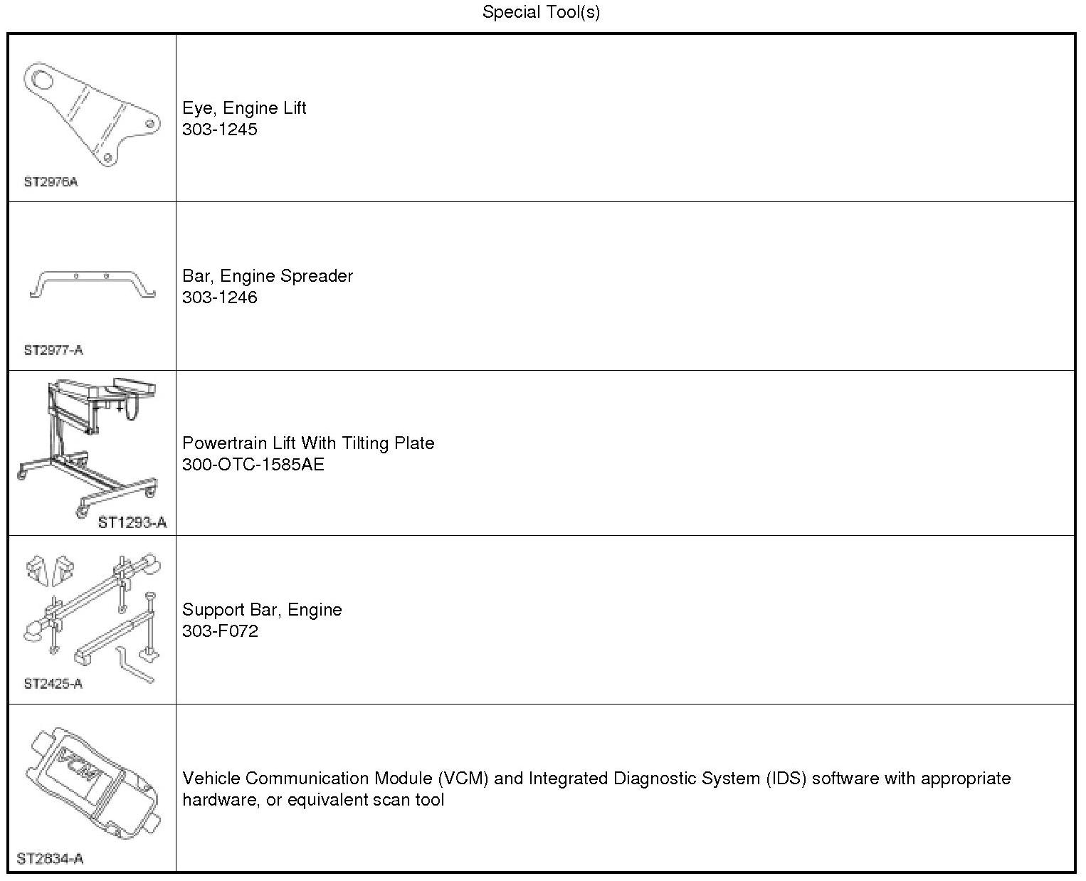
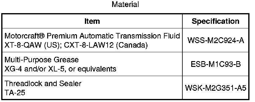
NOTICE: The use of any transmission fluid other than what is recommended for this transaxle will cause transaxle damage.
NOTE: If the transaxle was overhauled, or if installing a new transaxle and the transmission fluid cooler has not been flushed, flush the transmission fluid cooler at this time. For additional information, refer to Transmission Fluid Cooler - Backflushing and Cleaning Transmission Fluid Cooler Backflushing and Cleaning.
All vehicles
1. Secure the transaxle to a suitable transmission jack with a safety strap.
2. Prior to installing the transaxle, apply multi-purpose grease to the torque converter pilot hub.
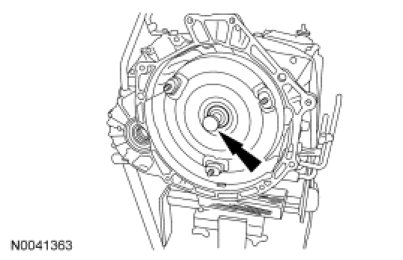
3. Position the transaxle to the back of the engine.
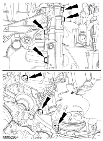
4. Install the 7 transaxle-to-engine bolts.
- Tighten to 48 Nm (35 lb-ft).
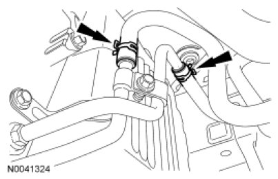
5. Connect the transmission fluid cooler hoses to the transmission cooler tubes.
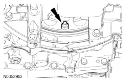
6. Install 4 new torque converter nuts.
- Tighten to 36 Nm (27 lb-ft).
7. Position the inspection cover in place and install the 2 fasteners.

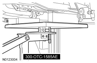
8. Using the Powertrain Lift With Tilting Plate, raise the subframe into the installed position.
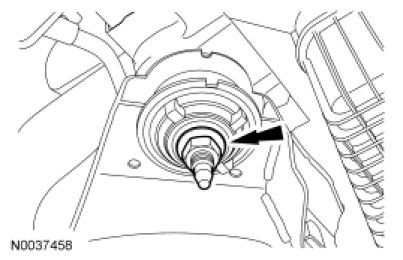
9. NOTE: LH shown, RH similar.
Install the 2 front subframe nuts.
- Tighten to 150 Nm (111 lb-ft).
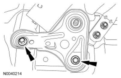
10. NOTE: LH shown, RH similar.
Position the subframe brackets and install the 4 bolts finger-tight.
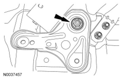
11. NOTE: LH shown, RH similar.
Install the 2 rear subframe nuts.
- Tighten to 150 Nm (111 lb-ft).
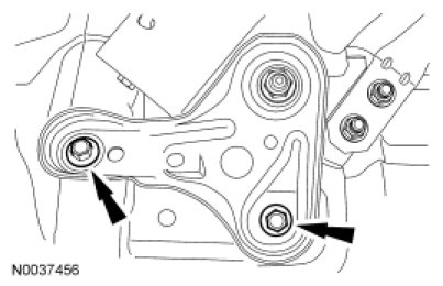
12. NOTE: LH shown, RH similar.
Tighten the 4 subframe bracket-to-body bolts to 103 Nm (76 lb-ft).
13. NOTICE: Use care when handling the steering gear to avoid unseating the steering gear/dash seal. If the steering gear/dash seal becomes unseated, water and foreign material may enter the passenger compartment and damage to the vehicle interior can occur.
Position the steering gear.
1. Install the 3 steering gear mounting bolts.
2. Tighten to 107 Nm (79 lb-ft).
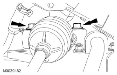
14. Install the 3 power steering return line bolts.
- Tighten to 9 Nm (80 lb-in).
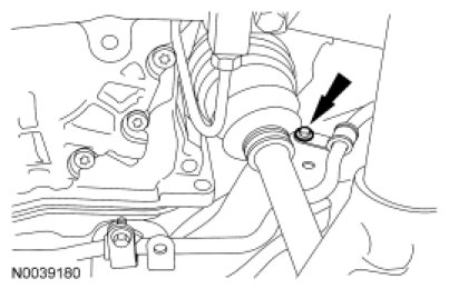
15. NOTE: LH shown, RH similar.
Install the stabilizer bar links and nuts to the struts.
- Tighten to 40 Nm (30 lb-ft).
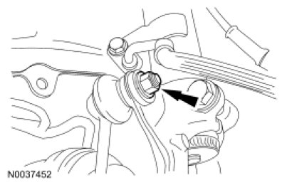
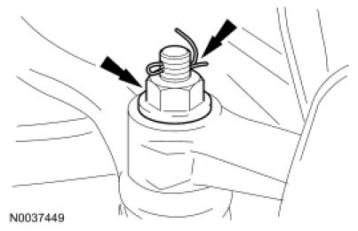
16. NOTE: LH shown, RH similar.
Install the tie-rod ends and nuts.
- Tighten to 48 Nm (35 lb-ft).
- Install new cotter pins.
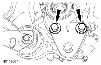
17. NOTE: Front Wheel Drive (FWD) shown, All-Wheel Drive (AWD) similar.
Install the 2 roll restrictor bracket bolts.
- Tighten to 90 Nm (66 lb-ft).
All-Wheel Drive (AWD) vehicles
18. Install the Power Transfer Unit (PTU). For additional information, refer to Transfer Case - Power Transfer Unit (PTU) Removal and Replacement.
Front Wheel Drive (FWD)
19. Install the exhaust flexible pipe. For additional information, refer to Exhaust System Service and Repair.
20. Install the RH intermediate shaft. For additional information, refer to Front Drive Halfshafts Intermediate Shaft.
All vehicles
21. Install the LH halfshaft. For additional information, refer to Front Drive Halfshafts Front Drive Halfshafts.
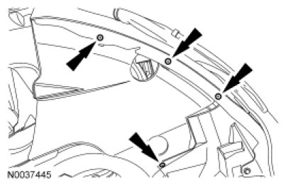
22. Install the LH splash shield and the 6 pin-type retainers (4 shown).

23. Position the LH fender splash shield and install the 4 screws.
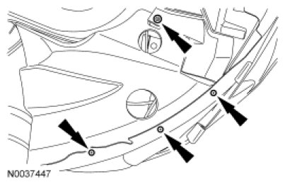
24. Install the RH splash shield and the 6 pin-type retainers (4 shown).
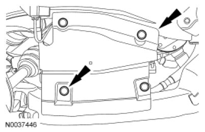
25. Position the RH fender splash shield and install the 4 screws.
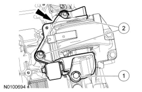
26. Apply threadlock and sealer to the threads and install the transaxle support insulator bracket, the 2 nuts and the bolt.
1. Tighten the bolt to 80 Nm (59 lb-ft).
2. Tighten the nuts to 90 Nm (66 lb-ft).
27. Using the Engine Support Bar, raise the transaxle. Apply threadlock and sealant to the threads and install the transaxle support insulator through bolt.
- Tighten to 150 Nm (111 lb-ft).
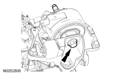
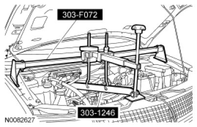
28. Remove the Engine Support Bar and Engine Spreader Bar.
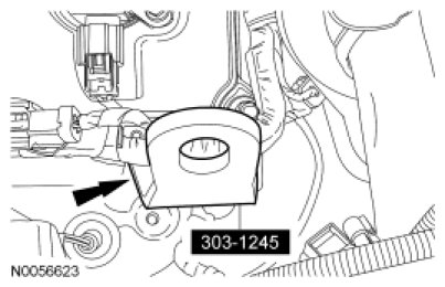
29. Remove the Engine Lift Eye from the LH cylinder head.
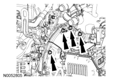
30. Install the 4 upper transaxle-to-engine bolts.
- Tighten to 48 Nm (35 lb-ft).
31. Position the 2 ground straps in place and install the 2 ground strap bolts.
- Tighten to 12 Nm (106 lb-in).
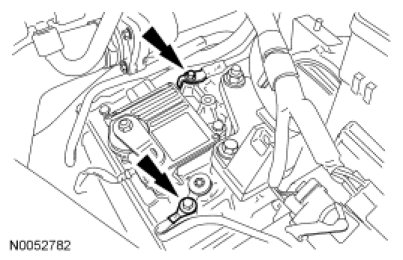
32. Connect the wiring harness fasteners on the torque converter housing stud bolt and the starter motor.
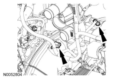
33. Connect the Transmission Control Module (TCM) electrical connector.
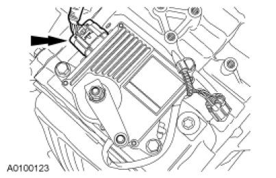
34. Position the selector lever cable bracket in place and install the 2 bolts and the nut.
- Tighten to 12 Nm (106 lb-in).
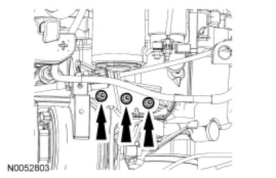
35. Connect the selector lever cable end.
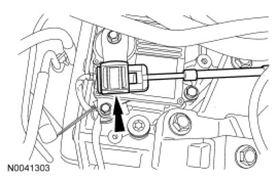
36. Remove the transmission fluid fill plug.
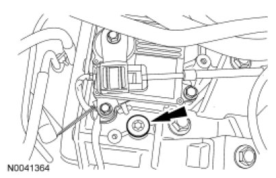
37. Fill the transaxle with clean transmission fluid.
38. Install the transmission fluid fill plug.
- Tighten to 39 Nm (29 lb-ft).
39. Install the upper intake manifold. For additional information, refer to Engine - 3.5L Upper Intake Manifold.
40. Install the starter for additional information, refer to Starting System Service and Repair.
41. Install the Air Cleaner (ACL) and outlet tube. For additional information, refer to Intake Air Distribution and Filtering - 3.5L Air Cleaner and Air Cleaner Outlet Pipe.
42. Remove the transmission fluid level indicator and make sure that the transaxle has transmission fluid in it.
43. With the transaxle in PARK, the vehicle on a level surface, the engine at idle (680-780 rpm) and foot pressed on the brake, move the selector lever through each gear and allow engagement of each gear. Place the selector lever back in the PARK position.
44. Wipe the transmission fluid level indicator cap and remove the transmission fluid level indicator.
45. Wipe the transmission fluid level indicator with a clean cloth.
46. NOTE: In order to get an accurate transmission fluid level reading the vehicle should be on a level surface. Idle the engine to reach the normal operating temperature. Using the scan tool, verify that the transaxle is at normal operating temperature 60°C-70°C (140°F-158°F), prior to adjusting the transmission fluid level.
If transmission fluid needs to be added, add transmission fluid in 0.25L (1/2 pt) increments through the transmission fluid fill plug located on the top of the transaxle near the transmission fluid level indicator. Do not overfill the transmission fluid. Install the transmission fluid level indicator back in the transmission fluid filler tube until it is fully seated, then remove the indicator. The transmission fluid level should be at the upper most mark on the transmission fluid level indicator. Only fill to the upper most mark on the transmission fluid level indicator. Do not overfill. Damage to the transaxle will occur.
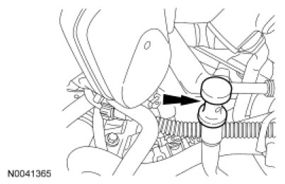
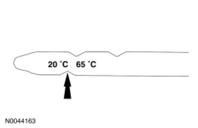
47. NOTE: The correct transmission fluid level at normal operating temperature of 60°C-70°C (140°F-158°F) is between the top 2 marks on the transmission fluid level indicator.
Fill the transaxle to the correct transmission fluid level.
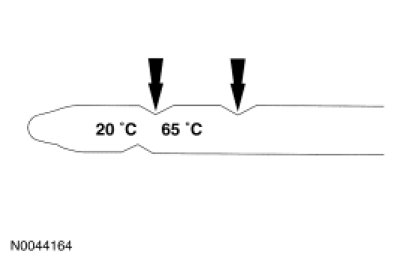
48. NOTE: The correct transmission fluid level at cold operating temperature of 15°C-25°C (59°F-77°F) is at the bottom mark on the transmission fluid level indicator.
If the Transmission Fluid Temperature (TFT) is low, fill the transaxle with transmission fluid to the cold range on the transmission fluid level indicator. Recheck the transmission fluid level when the transaxle has reached the normal operating temperature.
49. After completing the repairs, use the scan tool to perform the Misfire Monitor Neutral Profile Correction procedure, following the on-screen instructions.
Factory Service Tools
Use the Manual With the Right Hardware
Pair factory procedures with proven DIY tools so the instructions are easier to execute.
Disclosure: Verified tool recommendations may earn an affiliate commission at no cost to you.
When to See a Mechanic
Stop DIY work and contact a certified mechanic immediately if any of the following apply:
- • You smell fuel, burning insulation, or see smoke.
- • Brakes feel soft, pull hard to one side, or make grinding noises.
- • The engine overheats, stalls repeatedly, or misfires under load.
- • You are missing required tools, torque specs, or safe lifting equipment.
- • You are not confident in the next step or safety outcome.
Rather have a pro handle this?
A certified mobile mechanic comes to your home or office. They bring the tools, you stay comfortable. No tow truck, no waiting room, no surprises.
Comes to youSame-day available12-month warranty
Get a Free QuoteNo obligation. See pricing before you book.