
Safety Warning
DIY auto repair can cause serious injury, fire, or vehicle damage. These guides are for informational purposes only. Always follow OEM torque specs, wear PPE, and consult a certified mechanic if you are unsure. You are solely responsible for your safety.
2011 Mercury Milan AWD V6-3.0LFACTORY OEM SERVICE PROCEDURE
Diagnostic Aids
Troubleshooting wiring harness and connector hidden concerns
The illustrations are known examples of wiring harness, splices and connectors that will create intermittent electrical concerns. The concerns are hidden and can only be discovered by a physical evaluation as shown in each illustration.
NOTE: Several components, such as the PCM, utilize gold plated terminals in their connections to the wiring harness. If those terminals need to be replaced, they must be replaced with a gold plated terminal.
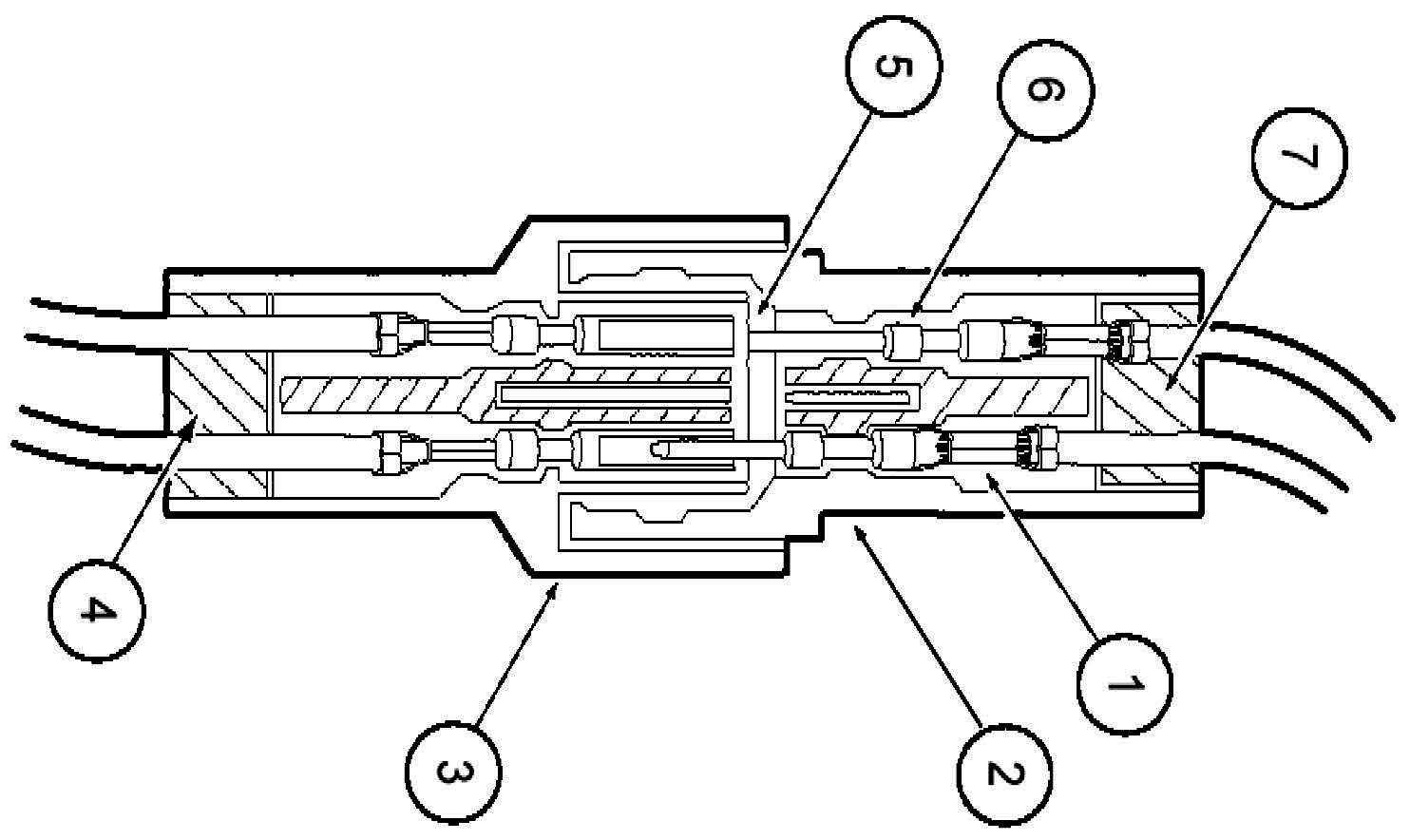
Terminal not properly seated
1 = Locked terminal
2 = Male half
3 = Female half
4 = Seal
5 = Intermittent contact
6 = Unlocked terminal (Hidden by wire seal)
7 = Seal
Check for unlocked terminal by pulling each wire at the end of the connector.
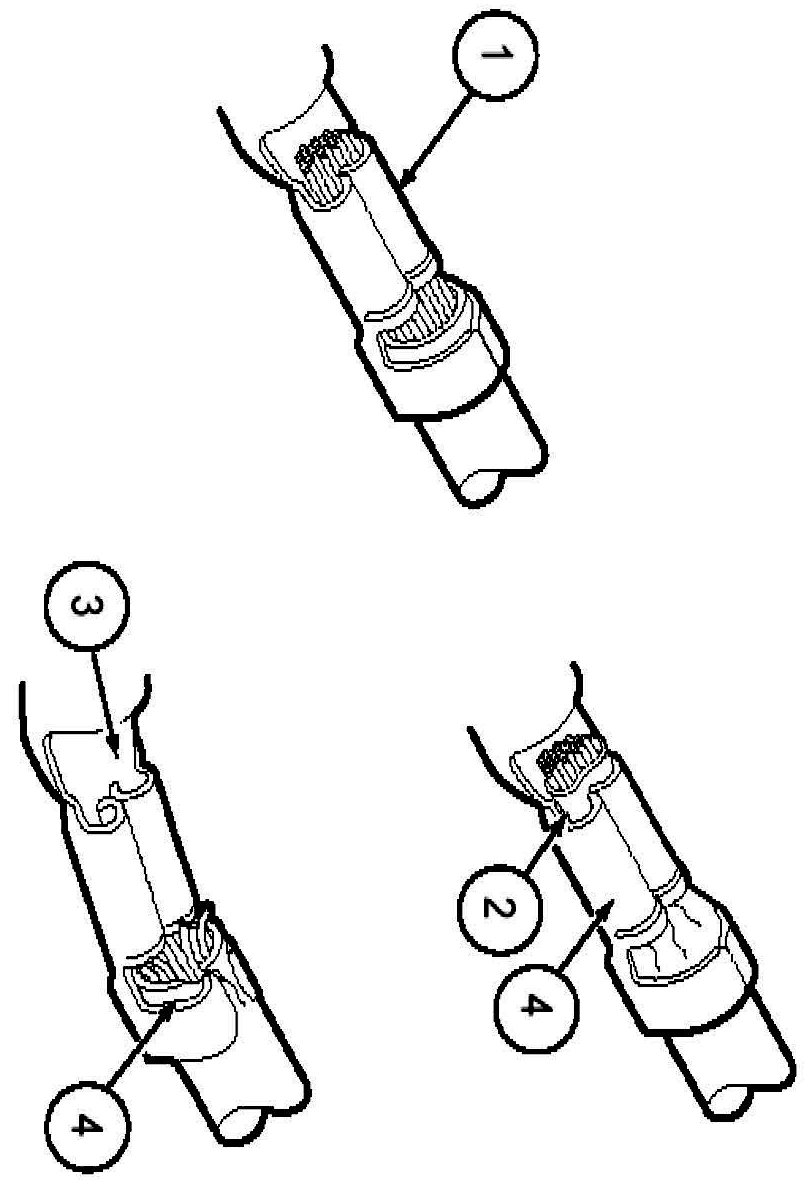
Defective insulation stripping
1 = Proper crimp
2 = Insulation not removed
3 = Wire strands missing
4 = Intermittent signals through pierced insulation
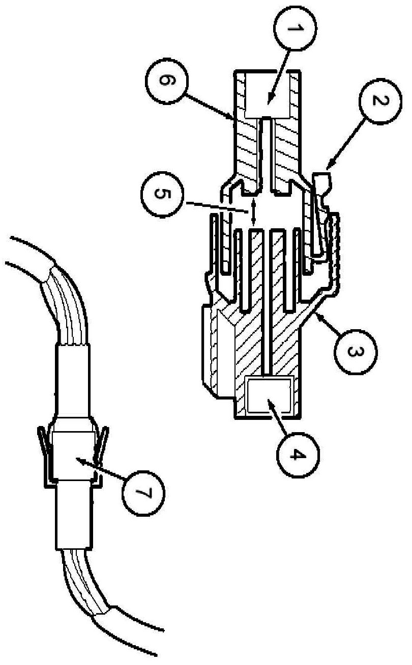
Partially mated connectors
1 = Seal
2 = Displaced tab
3 = Female half
4 = Seal
5 = Intermittent contact
6 = Male half
7 = Intermittent contact
Lock may be displaced into an unlocked position; pull on the connector to verify the lock.

Deformed (enlarged) female terminals
1 = Enlarged
2 = Normal
Any probe entering the terminal may enlarge the contact spring opening creating an intermittent signal.
Insert the correct mating terminal (Location A) from the service kit and feel for a loose fit.

Electrical short inside the harness
1 = Solder coated wire to ground
2 = Harness protective tape
3 = Intermittent short
Solder coated wire pierced through the insulation of another circuit
4 = Grounding foil
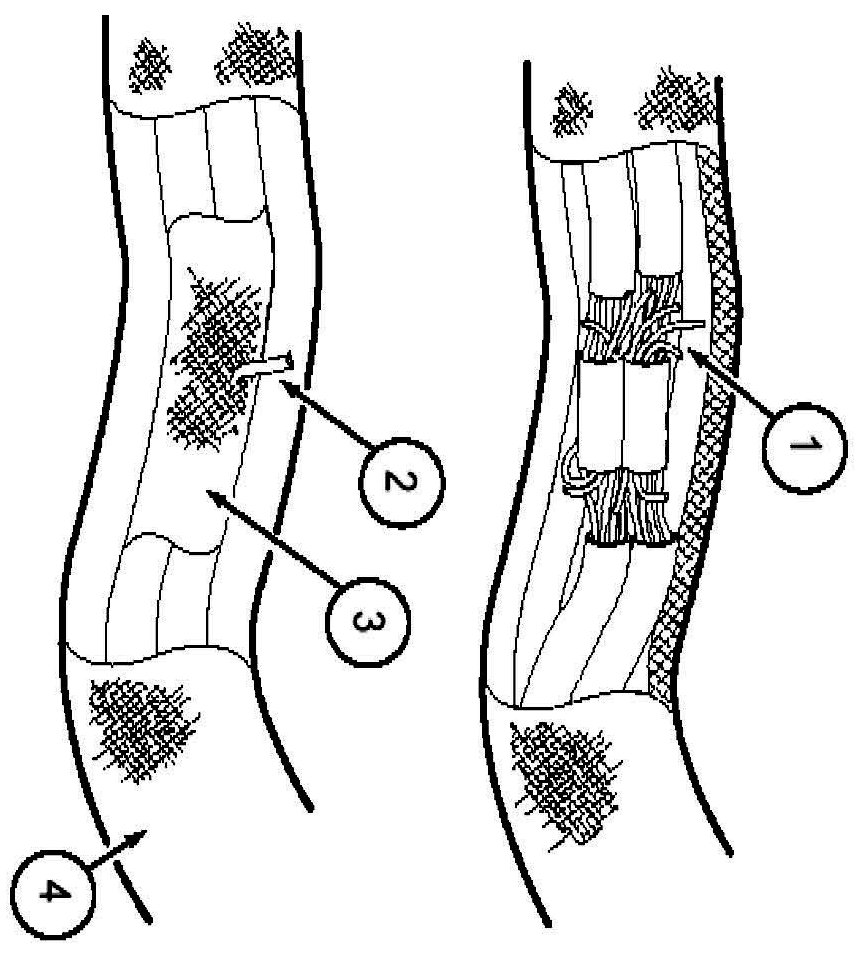
Electrical short within the harness
Splice tape removed
1 = Intermittent short
Splice covered
2 = Wire strand
3 = Splice tape
4 = Harness tape
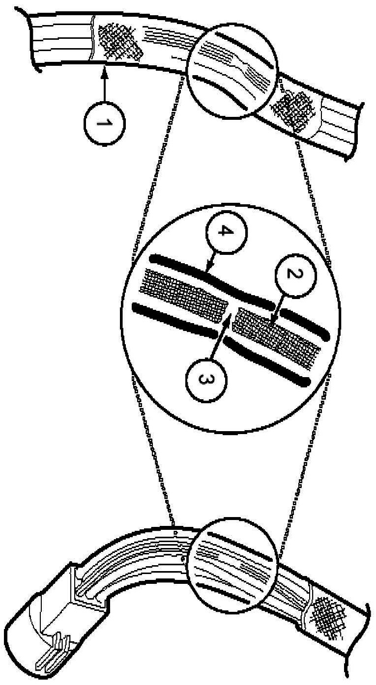
Broken wire strands in harness
1 = Wiring harness tape
2 = Wiring strand
3 = Broken strands intermittent signal
4 = Circuit insulation
Remove the tape and flex/feel each circuit for a reduction in diameter at break.
Recommended splicing method - Solder (For 16 AWG and Smaller Diameter Wire Only)
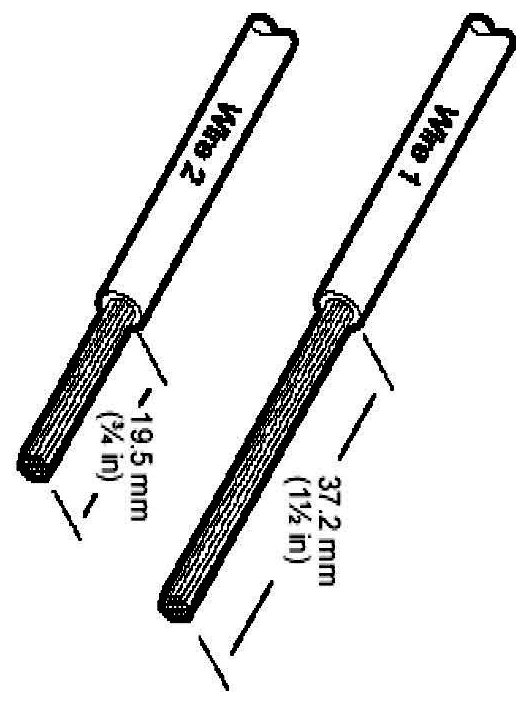
1. Disconnect battery ground cable.
2. Strip wires to appropriate length.
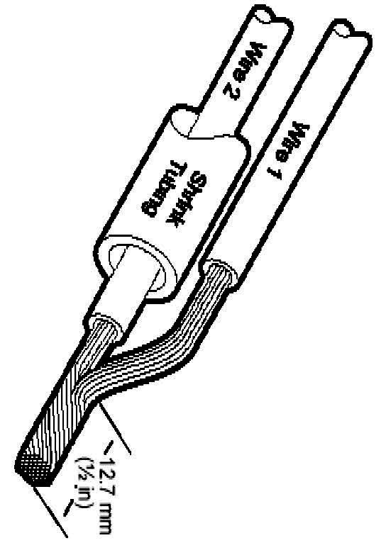
3. Install heat shrink tubing.
4. Twist wires together.
5. Solder wires together.
NOTE:
- Use rosin core mildly-activated (RMA) solder. Do not use acid core solder.
- Use heat shrinkable tubes marked with ES-1 (16-22 GA) or ES-2 (10-18 GA) to seat wire splice.
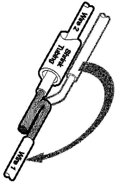
6. Bend wire 1 back in a straight line.
NOTE: Wait for solder to cool before moving wires.
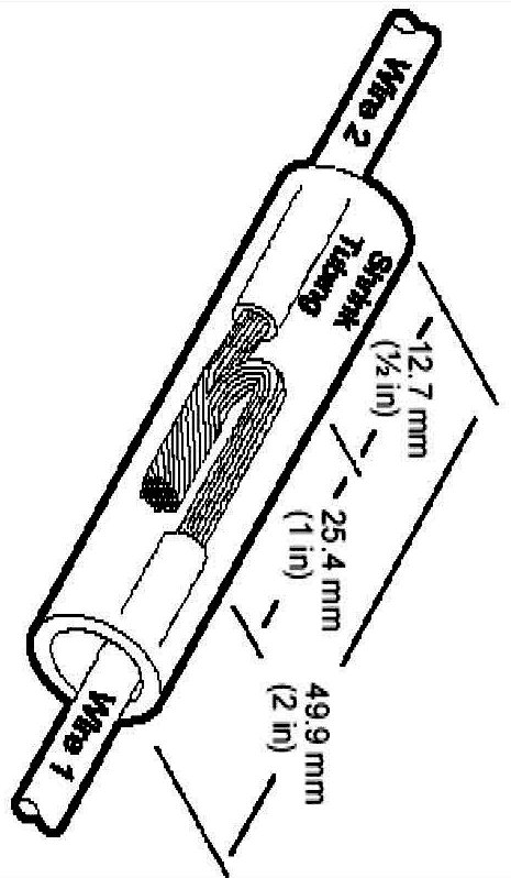
7. Evenly position heat shrink tubing over wire repair.
NOTE: Overlap tubing on both wires.
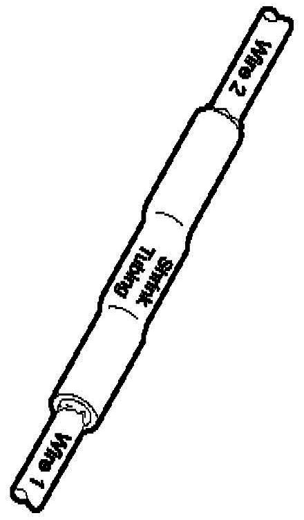
8. Use shielded heat gun to heat the repaired area until adhesive flows out of both ends of heat shrink tubing.
9. Reconnect battery ground cable.
Recommended splicing method - Crimp (For 10-22 AWG Diameter Wire to Like Wire Diameter)
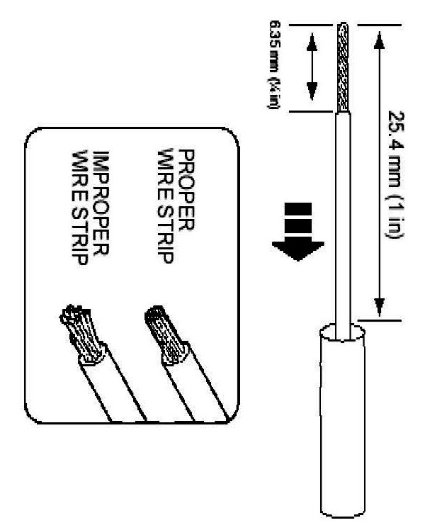
1. Disconnect battery ground cable.
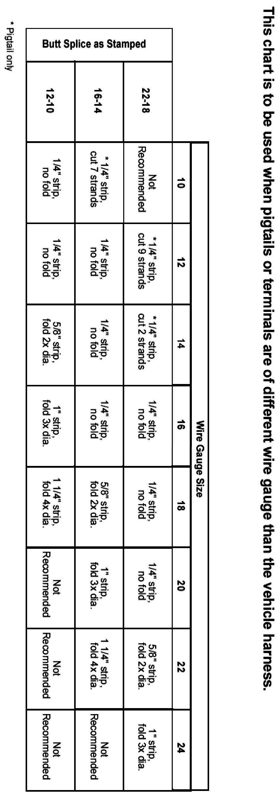
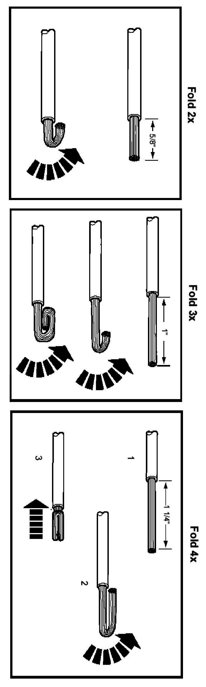
2. Strip 6.35mm (1/4 in) of insulation from each wire end, taking care not to nick or cut wire strands.
3. Install heat shrink tubing.
NOTE: Use heat shrinkable tubes marked with ES-1 (16-22 GA) or ES-2 (10-18 GA) to seal wire splice.

4. Select appropriate wire splice for the wires to be spliced.
5. Identify the appropriate crimping chamber on the Rotunda 164-R5901 Pro-Crimper by matching the wire size on the dies with the wire size stamped on the butt splice.
NOTE: Rotunda 164-R5901 Pro-Crimper is the only tool that can be used with these splices.
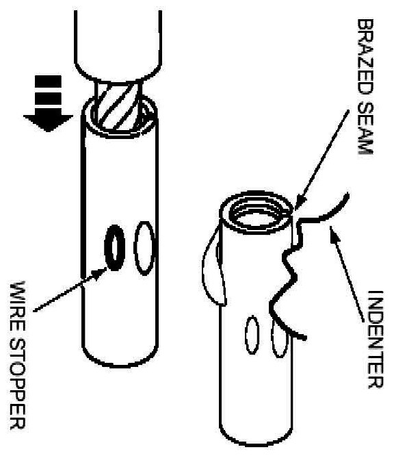
6. Center one end of the wire splice in the appropriate crimping chamber.
7. If visible, be sure to place the brazed seam toward the indenter.
8. Insert stripped wire into the barrel.
9. Holding the wire in place, barrel squeeze tool handles appropriate ratchet releases.
10. Repeating steps 5-7, crimp the other half of the splice.
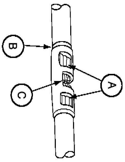
11. Check for acceptable crimp.
a. Crimp should be centered on each end of the butt splice
b. Wire insulation does not enter butt splice.
c. Wire is visible through inspection hole of splices.

12. Evenly position supplied heat shrink tubing over wire repair.
13. Use shielded heat gun to heat the repaired area until adhesive flows out of both ends of the heat shrink tubing.
14. Reconnect battery ground cable.
The illustrations are known examples of wiring harness, splices and connectors that will create intermittent electrical concerns. The concerns are hidden and can only be discovered by a physical evaluation as shown in each illustration.
NOTE: Several components, such as the PCM, utilize gold plated terminals in their connections to the wiring harness. If those terminals need to be replaced, they must be replaced with a gold plated terminal.
Terminal not properly seated
1 = Locked terminal
2 = Male half
3 = Female half
4 = Seal
5 = Intermittent contact
6 = Unlocked terminal (Hidden by wire seal)
7 = Seal
Check for unlocked terminal by pulling each wire at the end of the connector.
Defective insulation stripping
1 = Proper crimp
2 = Insulation not removed
3 = Wire strands missing
4 = Intermittent signals through pierced insulation
Partially mated connectors
1 = Seal
2 = Displaced tab
3 = Female half
4 = Seal
5 = Intermittent contact
6 = Male half
7 = Intermittent contact
Lock may be displaced into an unlocked position; pull on the connector to verify the lock.
Deformed (enlarged) female terminals
1 = Enlarged
2 = Normal
Any probe entering the terminal may enlarge the contact spring opening creating an intermittent signal.
Insert the correct mating terminal (Location A) from the service kit and feel for a loose fit.
Electrical short inside the harness
1 = Solder coated wire to ground
2 = Harness protective tape
3 = Intermittent short
Solder coated wire pierced through the insulation of another circuit
4 = Grounding foil
Electrical short within the harness
Splice tape removed
1 = Intermittent short
Splice covered
2 = Wire strand
3 = Splice tape
4 = Harness tape
Broken wire strands in harness
1 = Wiring harness tape
2 = Wiring strand
3 = Broken strands intermittent signal
4 = Circuit insulation
Remove the tape and flex/feel each circuit for a reduction in diameter at break.
Recommended splicing method - Solder (For 16 AWG and Smaller Diameter Wire Only)
1. Disconnect battery ground cable.
2. Strip wires to appropriate length.
3. Install heat shrink tubing.
4. Twist wires together.
5. Solder wires together.
NOTE:
- Use rosin core mildly-activated (RMA) solder. Do not use acid core solder.
- Use heat shrinkable tubes marked with ES-1 (16-22 GA) or ES-2 (10-18 GA) to seat wire splice.
6. Bend wire 1 back in a straight line.
NOTE: Wait for solder to cool before moving wires.
7. Evenly position heat shrink tubing over wire repair.
NOTE: Overlap tubing on both wires.
8. Use shielded heat gun to heat the repaired area until adhesive flows out of both ends of heat shrink tubing.
9. Reconnect battery ground cable.
Recommended splicing method - Crimp (For 10-22 AWG Diameter Wire to Like Wire Diameter)
1. Disconnect battery ground cable.
2. Strip 6.35mm (1/4 in) of insulation from each wire end, taking care not to nick or cut wire strands.
3. Install heat shrink tubing.
NOTE: Use heat shrinkable tubes marked with ES-1 (16-22 GA) or ES-2 (10-18 GA) to seal wire splice.
4. Select appropriate wire splice for the wires to be spliced.
5. Identify the appropriate crimping chamber on the Rotunda 164-R5901 Pro-Crimper by matching the wire size on the dies with the wire size stamped on the butt splice.
NOTE: Rotunda 164-R5901 Pro-Crimper is the only tool that can be used with these splices.
6. Center one end of the wire splice in the appropriate crimping chamber.
7. If visible, be sure to place the brazed seam toward the indenter.
8. Insert stripped wire into the barrel.
9. Holding the wire in place, barrel squeeze tool handles appropriate ratchet releases.
10. Repeating steps 5-7, crimp the other half of the splice.
11. Check for acceptable crimp.
a. Crimp should be centered on each end of the butt splice
b. Wire insulation does not enter butt splice.
c. Wire is visible through inspection hole of splices.
12. Evenly position supplied heat shrink tubing over wire repair.
13. Use shielded heat gun to heat the repaired area until adhesive flows out of both ends of the heat shrink tubing.
14. Reconnect battery ground cable.
Factory Service Tools
Use the Manual With the Right Hardware
Pair factory procedures with proven DIY tools so the instructions are easier to execute.
Disclosure: Verified tool recommendations may earn an affiliate commission at no cost to you.
When to See a Mechanic
Stop DIY work and contact a certified mechanic immediately if any of the following apply:
- • You smell fuel, burning insulation, or see smoke.
- • Brakes feel soft, pull hard to one side, or make grinding noises.
- • The engine overheats, stalls repeatedly, or misfires under load.
- • You are missing required tools, torque specs, or safe lifting equipment.
- • You are not confident in the next step or safety outcome.
Rather have a pro handle this?
A certified mobile mechanic comes to your home or office. They bring the tools, you stay comfortable. No tow truck, no waiting room, no surprises.
Comes to youSame-day available12-month warranty
Get a Free QuoteNo obligation. See pricing before you book.