
Safety Warning
DIY auto repair can cause serious injury, fire, or vehicle damage. These guides are for informational purposes only. Always follow OEM torque specs, wear PPE, and consult a certified mechanic if you are unsure. You are solely responsible for your safety.
2011 Mercury Milan AWD V6-3.0LFACTORY OEM SERVICE PROCEDURE
Steps 46-99
Engine
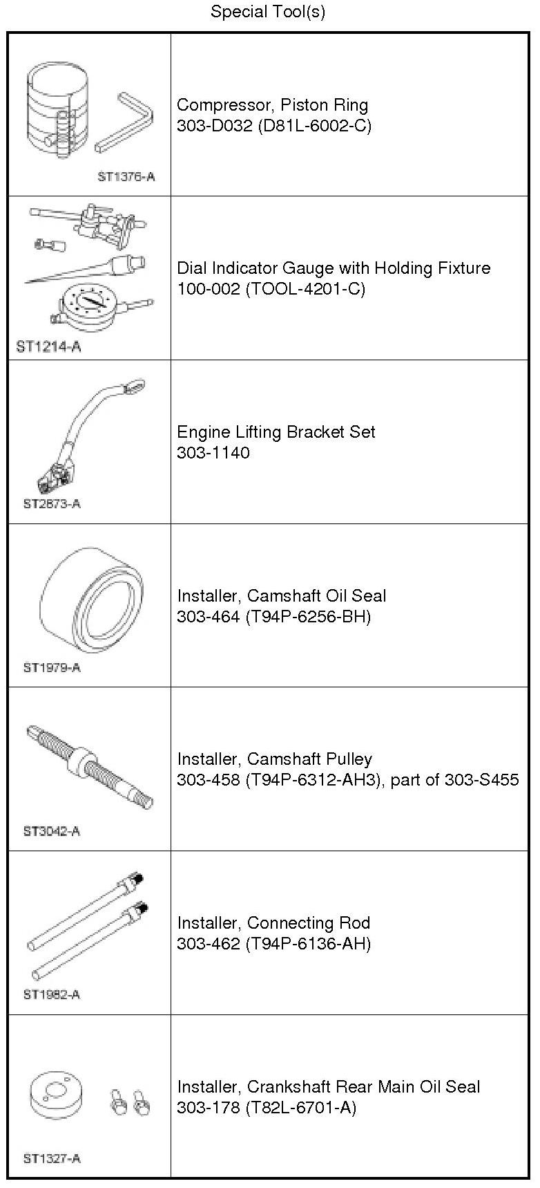
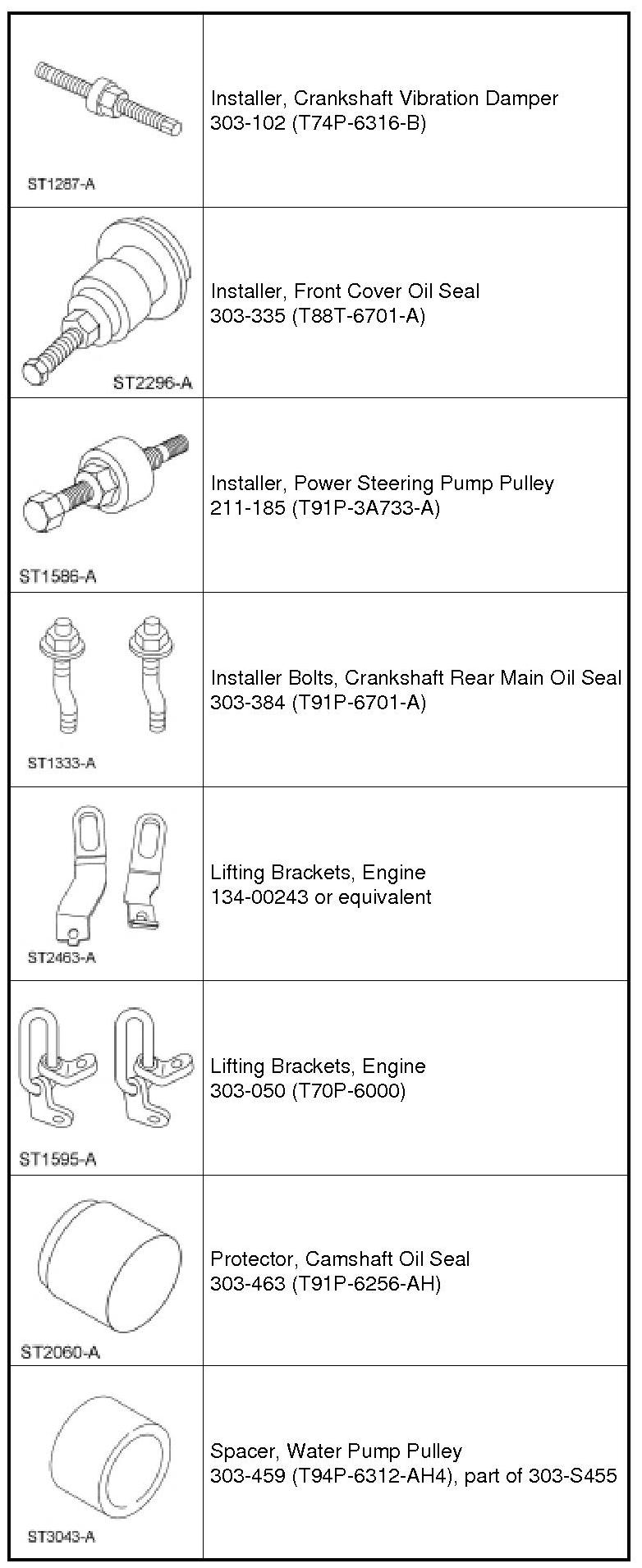

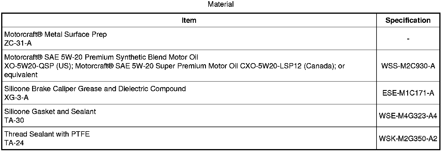
Lower Engine Block (View 1)
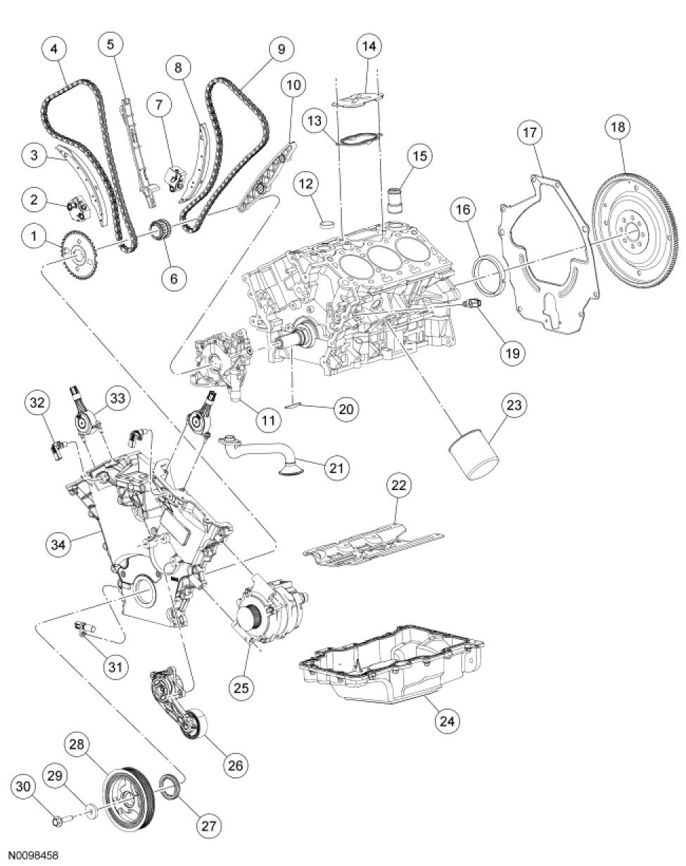
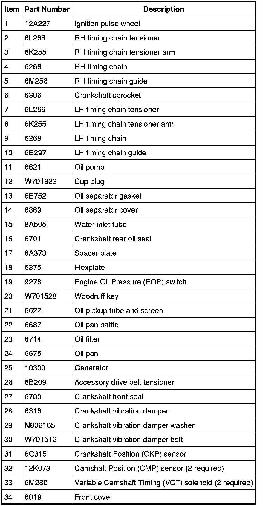
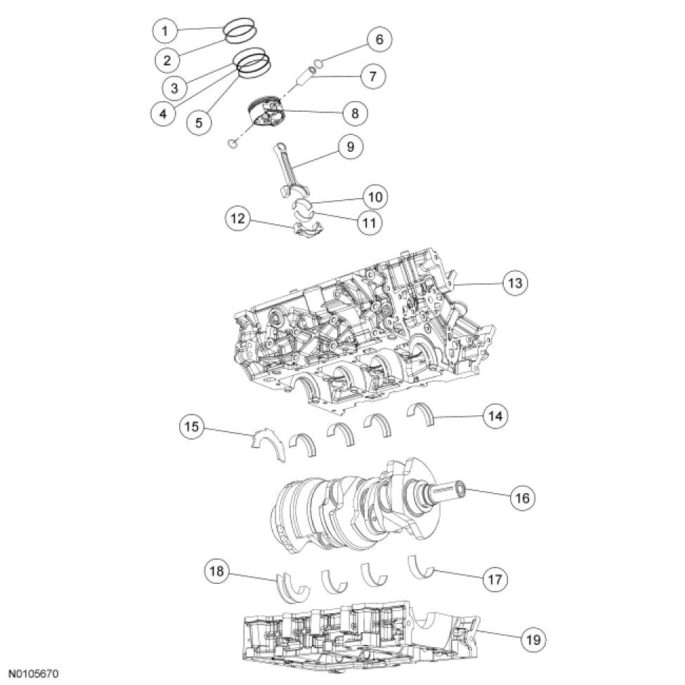
Lower Engine Block (View 2)
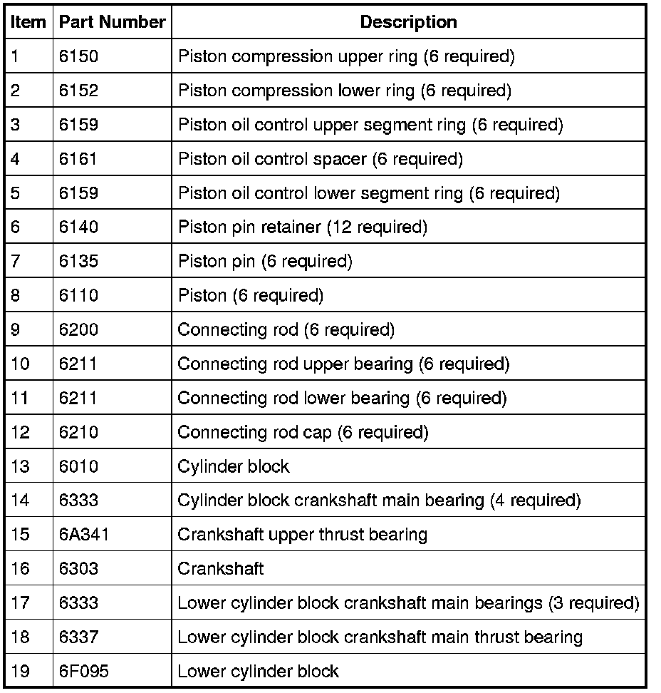
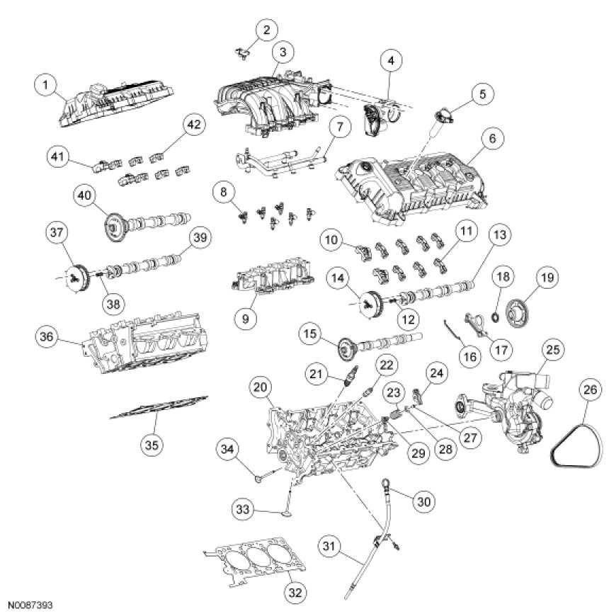
Cylinder Heads and Intake Manifolds

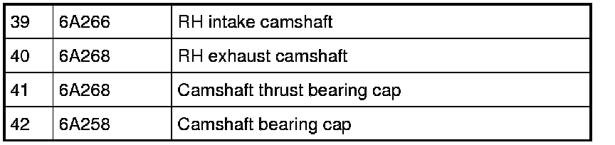
NOTICE: During engine repair procedures, cleanliness is extremely important. All parts must be thoroughly cleaned and any foreign material, including any material created while cleaning gasket surfaces, that enters the oil passages, coolant passages or the oil pan, can cause engine failure.
NOTICE: If the oil pan was removed during engine disassembly, it must be installed after the engine and transaxle are assembled and the transaxle-to-engine bolts are installed. Failure to follow this assembly sequence can result in engine oil leaks.
NOTE: Assembly of the engine requires various inspections/measurements of the engine components (engine block, crankshaft, connecting rods, pistons and piston rings). These inspections/measurements will aid in determining if the engine components will require replacement. For additional information, refer to Engine System - General Information Procedures.
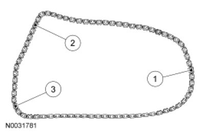
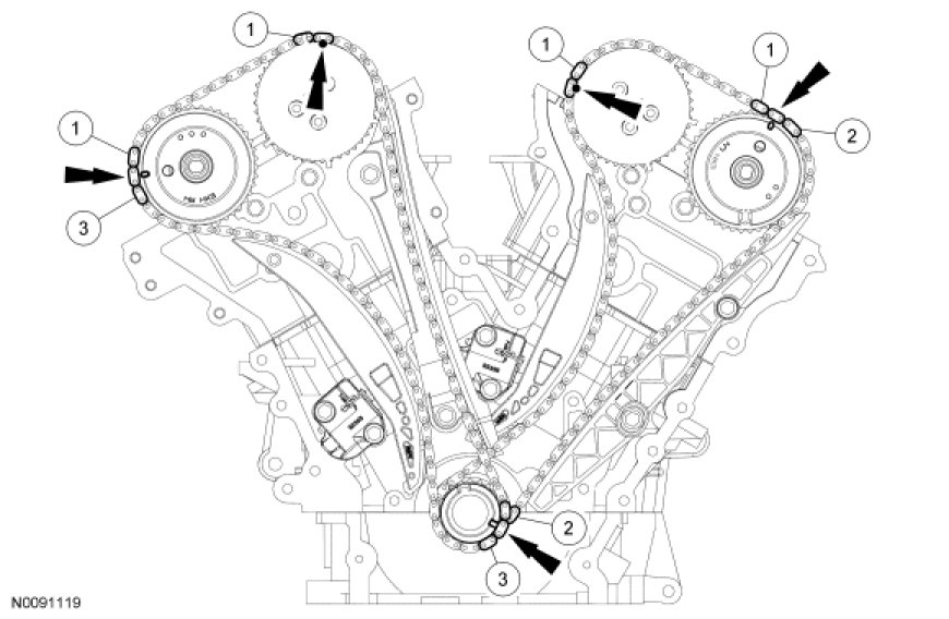
46. If timing marks in the timing chains are not evident, use a permanent-type marker to mark the crankshaft and camshaft timing marks on the LH and RH timing chains.
1. Mark any link to use as the crankshaft timing mark.
2. Starting with the crankshaft timing mark, count 29 links and mark the link.
3. Continue counting to link 42 and mark the link.
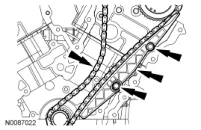
47. Position the LH timing chain and guide and install the bolts.
- Tighten to 25 Nm (18 lb-ft).
- Align the marks on the timing chain with the marks on the camshaft and crankshaft sprockets.
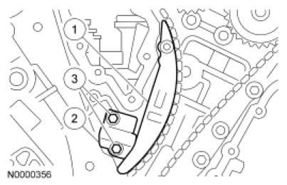
48. Install the LH timing chain tensioner arm and the LH timing chain tensioner.
1. Install the tensioner arm.
2. Position the tensioner.
3. Install the bolts.
- Tighten to 25 Nm (18 lb-ft).
49. Install the crankshaft pulley bolt and rotate the crankshaft clockwise 120 degrees until the crankshaft keyway is in the 3 o'clock position.
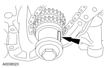
50. Verify that the RH camshafts are correctly positioned.
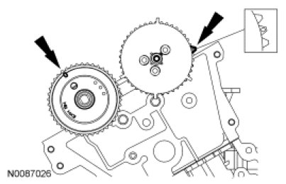
51. Install the RH timing chain and chain guide and install the bolts.
- Tighten to 25 Nm (18 lb-ft).
- Align the marks on the timing chain with the marks on the camshaft and crankshaft sprockets.
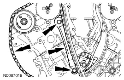
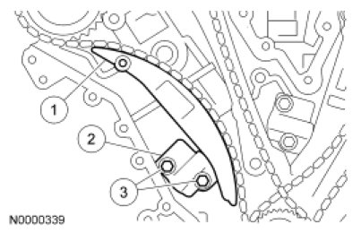
52. Install the RH timing chain tensioner and tensioner arm.
1. Install the tensioner arm.
2. Position the tensioner.
3. Install the bolts.
- Tighten to 25 Nm (18 lb-ft).
53. Remove the LH and RH timing chain tensioner piston retaining wires.
54. Rotate the crankshaft counterclockwise 120 degrees to TDC.
55. NOTICE: Failure to verify correct timing drive component alignment will result in severe engine damage.
Verify the timing with the following steps.
1. There should be 12 chain links between the camshaft timing marks.
2. There should be 27 chain links between the camshaft and the crankshaft timing marks.
3. There should be 30 chain links between the camshaft and the crankshaft timing marks.
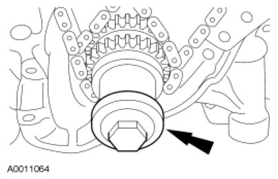
56. Remove the crankshaft pulley bolt and washer.
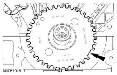
57. NOTE: This pulse wheel is used in several different engines. Install the pulse wheel with the keyway in the slot stamped "30RFF" only (orange in color).
Install the ignition pulse wheel.
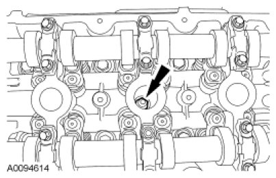
58. NOTICE: Only use hand tools when removing or installing the spark plugs, damage can occur to the cylinder head or spark plug.
Install the LH and RH spark plugs.
- Tighten to 15 Nm (133 lb-in).
59. NOTICE: Do not use metal scrapers, wire brushes, power abrasive discs or other abrasive means to clean the sealing surfaces. These tools cause scratches and gouges which make leak paths.
NOTICE: Do not damage the oil pan gasket while cleaning the sealant from the lower cylinder block-to-oil pan joint.
Use a plastic scraping tool to remove all traces of sealant.
- Clean all sealing surfaces with metal surface prep and install new gaskets.
60. NOTE: Clean and degrease the sealing surfaces with metal surface prep before applying gasket and sealant.
NOTE: The front cover must be installed and the bolts tightened within 4 minutes of sealant application.
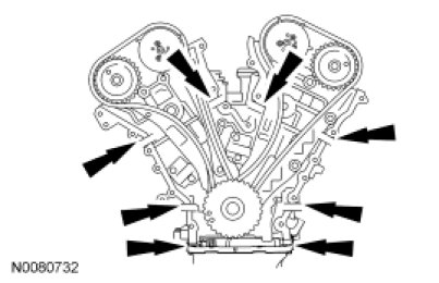
Apply a 6 mm (0.24 in) dot of silicone gasket and sealant to the cylinder block to lower cylinder block and cylinder head mating surfaces.
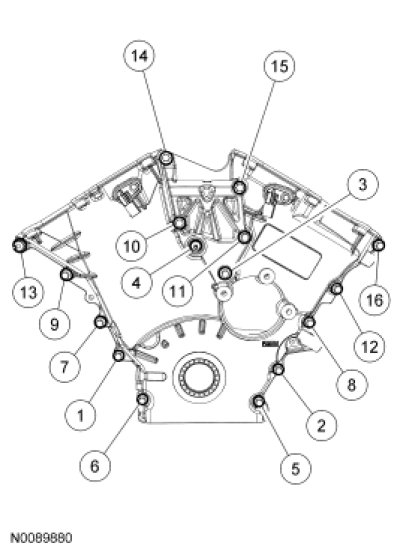
61. NOTE: Fasteners 4 and 13 are stud bolts.
Position the front cover and install the bolts and stud bolts.
- Tighten in the sequence shown to 25 Nm (18 lb-ft).
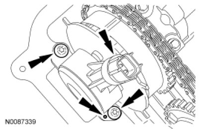
62. NOTE: Note the position of the alignment dowel on the engine front cover.
Install the 2 bolts and the LH Variable Camshaft Timing (VCT) solenoid.
- Tighten to 10 Nm (89 lb-in).
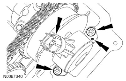
63. NOTE: Note the position of the alignment dowel on the engine front cover.
Install the 2 bolts and the RH VCT solenoid.
- Tighten to 10 Nm (89 lb-in).
64. NOTE: Clean all sealing surfaces with metal surface prep.
Apply clean engine oil to the seal lip and seal bore before installing the seal.
65. Using the Front Cover Oil Seal Installer and the Crankshaft Vibration Damper Installer, install a new crankshaft front seal.
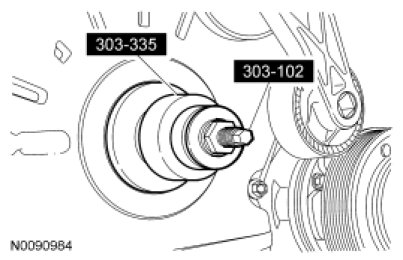
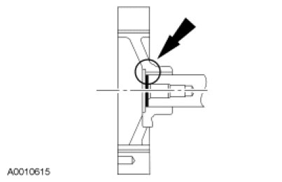
66. NOTE: Clean the keyway and slot using metal surface prep before applying silicone gasket and sealant.
NOTE: Sealing surfaces must be free of dirt and oil.
NOTE: The crankshaft pulley must be installed and the bolt tightened within 4 minutes of sealant application.
Apply silicone gasket and sealant to the end of the crankshaft pulley keyway slot.
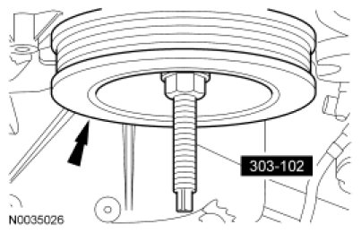
67. NOTE: Lubricate the outside diameter sealing surface with clean engine oil.
Using the Crankshaft Vibration Damper Installer, install the crankshaft pulley.
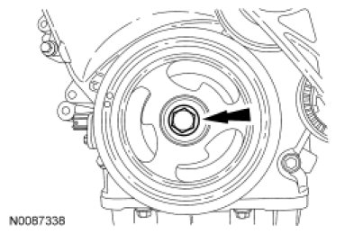
68. Install the bolt and washer. Tighten the bolt in 4 stages:
- Stage 1: Tighten to 120 Nm (89 lb-ft).
- Stage 2: Loosen one full turn.
- Stage 3: Tighten to 50 Nm (37 lb-ft).
- Stage 4: Tighten an additional 90 degrees.
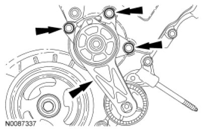
69. Install the belt tensioner and the 3 bolts.
- Tighten to 25 Nm (18 lb-ft).
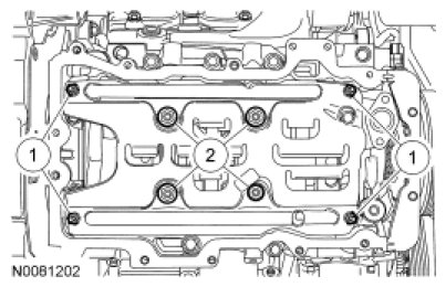
70. Install the 8 nuts and the oil pan baffle.
1. Tighten the 4 M6 oil pan baffle nuts in 2 stages.
- Stage 1: Tighten to 5 Nm (44 lb-in).
- Stage 2: Tighten an additional 45 degrees.
2. Then install and tighten the 4 M8 oil pan baffle nuts in 2 stages.
- Stage 1: Tighten to 15 Nm (133 lb-in).
- Stage 2: Tighten an additional 45 degrees.
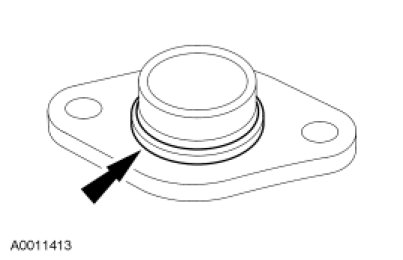
71. Install a new O-ring seal on the oil pump screen and pickup tube.
- Lubricate the O-ring seal with clean engine oil.
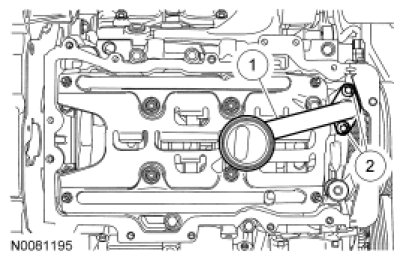
72. Install the oil pump screen and pickup tube.
1. Position the oil pump screen and pickup tube.
2. Install the 2 bolts and tighten to 10 Nm (89 lb-in).
73. Install the new gasket in the LH valve cover in the following sequence.
1. Install the gasket at waffle pads and then the corners.
2. Install the gasket around bolt holes.
3. Install the remaining part of the gasket.
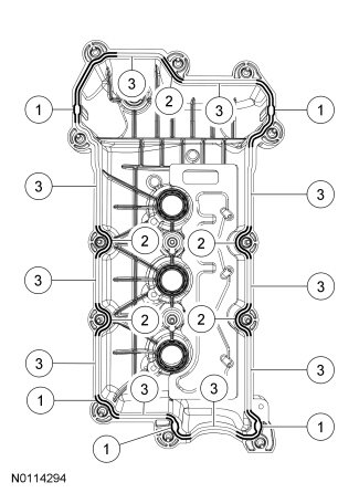
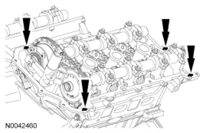
74. NOTE: The valve cover must be installed and the bolts and studs tightened within 4 minutes of sealant application.
NOTE: Clean cylinder head and front cover surface and the cam seal retainer-to-cylinder head surface using metal surface prep before applying silicone gasket and sealant.
Apply an 8 mm (0.31 in) dot of silicone gasket and sealant at the cylinder block to front cover mating surface and the cam seal retainer-to-cylinder head joints.
75. NOTE: Install a new valve cover gasket.
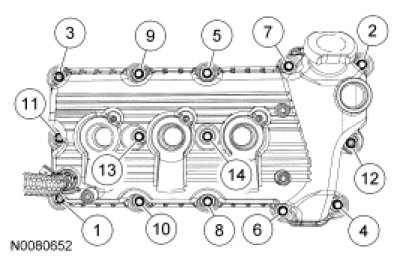
Position the LH valve cover and install the bolts and stud bolts.
- Tighten in the sequence shown to 10 Nm (89 lb-in).

76. Install the new gasket in the RH valve cover in the following sequence.
1. Install the gasket at waffle pads and then the corners.
2. Install the gasket around bolt holes.
3. Install the remaining part of the gasket.
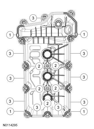
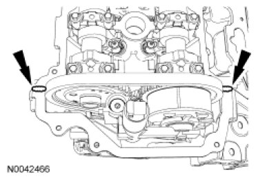
77. NOTE: The valve cover must be installed and the bolts and stud bolts tightened within 4 minutes of sealant application.
NOTE: Clean cylinder head and front cover surface using metal surface prep before applying silicone gasket and sealant.
Apply an 8 mm (0.31 in) dot of silicone gasket sealant to the front cover-to-cylinder head joints.
78. NOTE: Install a new valve cover gasket.
Position the RH valve cover and install the bolts and stud bolts.
- Tighten in the sequence shown to 10 Nm (89 lb-in).
79. If equipped, install the block heater.
- Tighten to 21 Nm (15 lb-ft).
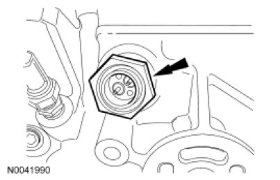
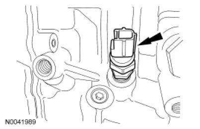
80. NOTE: Apply thread sealant with PTFE to the Engine Oil Pressure (EOP) switch threads.
Install the EOP switch.
- Tighten to 14 Nm (124 lb-in).
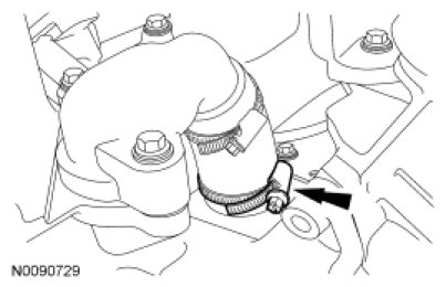
81. Position the coolant pump housing and attach the coolant hose.
- Tighten the clamp to 7 Nm (62 lb-in).
82. Install the 5 coolant pump housing bolts.
- Tighten to 10 Nm (89 lb-in).
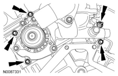
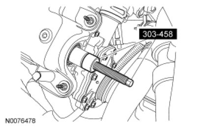
83. NOTICE: Failure to use the correct special tools, assembled as shown in the illustration, will result in damage to the coolant pump pulley and/or special tools.
Install the Camshaft Pulley Installer in the camshaft as shown in the illustration.
- Adjust the collar on the Camshaft Pulley Installer screw to get the best thread engagement in the rear of the camshaft.
84. NOTICE: Failure to use the correct special tools, assembled as shown in the illustration, will result in damage to the coolant pump pulley and/or special tools.
NOTE: Only the roller collared nut from the Power Steering Pump Pulley Installer (211-185) is used on Camshaft Pulley Installer (303-485).
Position the coolant pump pulley over the previously installed Camshaft Pulley Installer and on the end of the camshaft. Install the Camshaft Pulley Installer, Power Steering Pump Pulley Installer and the Water Pump Pulley Spacer as shown in the illustration.
- Using the Camshaft Pulley Installer, Power Steering Pump Pulley Installer and the Water Pump Pulley Spacer, install a new service coolant pump pulley flush with the end of the camshaft.

85. Install the coolant pump belt on the coolant pump pulley and position it on the camshaft pulley.
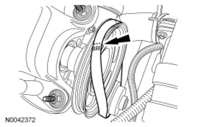
86. NOTICE: Do not use any screwdrivers, pliers or other metal objects that could cause damage to the belt or camshaft pulley while installing the belt.
Rotate the crankshaft clockwise to seat the water pump belt on the camshaft pulley.
87. Install a new O-ring on the oil level indicator tube. Apply clean engine oil to the O-ring.
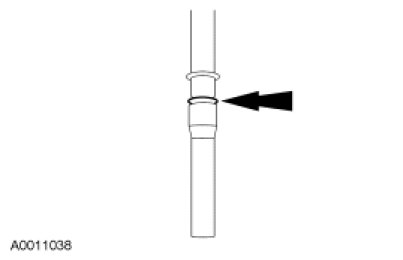
88. Position the oil level indicator and tube and install the stud bolt.
- Tighten to 9 Nm (80 lb-in).
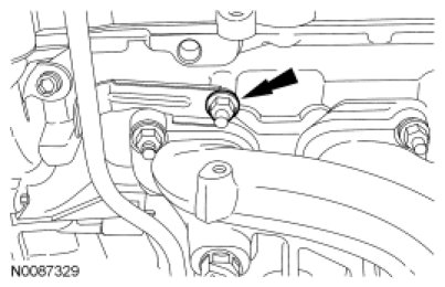
89. Install the 3 bolts and the A/C compressor bracket.
- Tighten to 25 Nm (18 lb-ft).
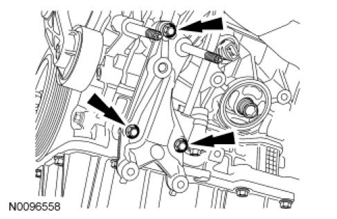
90. Lubricate the O-ring seal with clean engine oil and install the oil filter.
- Tighten to 5 Nm (44 lb-in) and then rotate an additional 180 degrees.
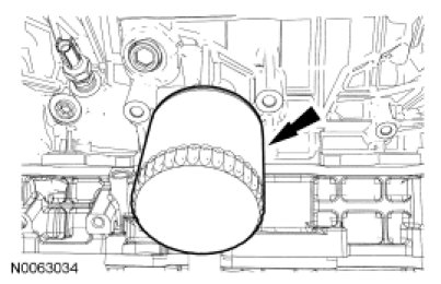
91. Position the generator and install the bolt and 2 nuts.
- Tighten to 47 Nm (35 lb-ft).
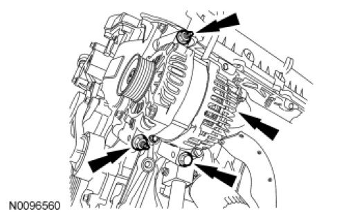
92. Install the A/C compressor and the 3 bolts.
- Tighten to 25 Nm (18 lb-ft).
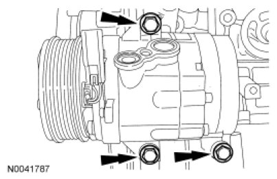
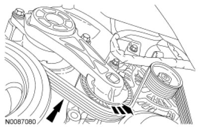
93. Rotate the accessory drive belt tensioner counterclockwise and install the accessory drive belt.
94. Install 6 new RH exhaust manifold studs.
- Tighten to 12 Nm (106 lb-in).
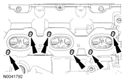
95. Install a new gasket and the RH exhaust manifold and new nuts.
- Tighten the nuts in 2 stages in the sequence shown.
- Stage 1: Tighten to 20 Nm (177 lb-in).
- Stage 2: Tighten to 20 Nm (177 lb-in).

Front Wheel Drive (FWD)
96. Install a new gasket and the RH catalytic converter and the 3 new nuts.
- Tighten to 40 Nm (30 lb-ft).

97. Install the 3 bolts and the RH heat shield.
- Tighten to 10 Nm (89 lb-in).
All engines
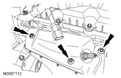
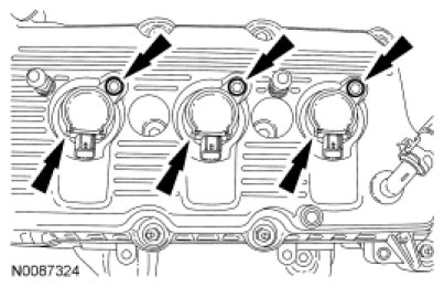
98. NOTE: LH shown, RH similar.
Apply a light film of silicone brake caliper grease and dielectric compound to the interior of the spark plug boot prior to installation.
Install the 6 coil-on-plugs and the bolts.
- Tighten to 6 Nm (53 lb-in).
99. NOTICE: If the engine is repaired or replaced because of upper engine failure, typically including valve or piston damage, check the intake manifold for metal debris. If metal debris is found, install a new intake manifold. Failure to follow these instructions can result in engine damage.
NOTE: Clean and inspect all sealing surfaces. Install new gaskets.
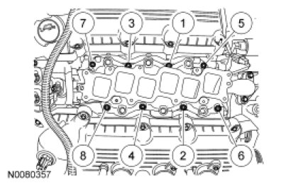
Position the lower intake manifold and install the 8 bolts.
- Tighten in the sequence shown to 10 Nm (89 lb-in).
Factory Service Tools
Use the Manual With the Right Hardware
Pair factory procedures with proven DIY tools so the instructions are easier to execute.
Disclosure: Verified tool recommendations may earn an affiliate commission at no cost to you.
When to See a Mechanic
Stop DIY work and contact a certified mechanic immediately if any of the following apply:
- • You smell fuel, burning insulation, or see smoke.
- • Brakes feel soft, pull hard to one side, or make grinding noises.
- • The engine overheats, stalls repeatedly, or misfires under load.
- • You are missing required tools, torque specs, or safe lifting equipment.
- • You are not confident in the next step or safety outcome.
Rather have a pro handle this?
A certified mobile mechanic comes to your home or office. They bring the tools, you stay comfortable. No tow truck, no waiting room, no surprises.
Comes to youSame-day available12-month warranty
Get a Free QuoteNo obligation. See pricing before you book.