
Safety Warning
DIY auto repair can cause serious injury, fire, or vehicle damage. These guides are for informational purposes only. Always follow OEM torque specs, wear PPE, and consult a certified mechanic if you are unsure. You are solely responsible for your safety.
2006 Mercury Mariner 4WD V6-3.0L VIN 1FACTORY OEM SERVICE PROCEDURE
Part 1
Engine
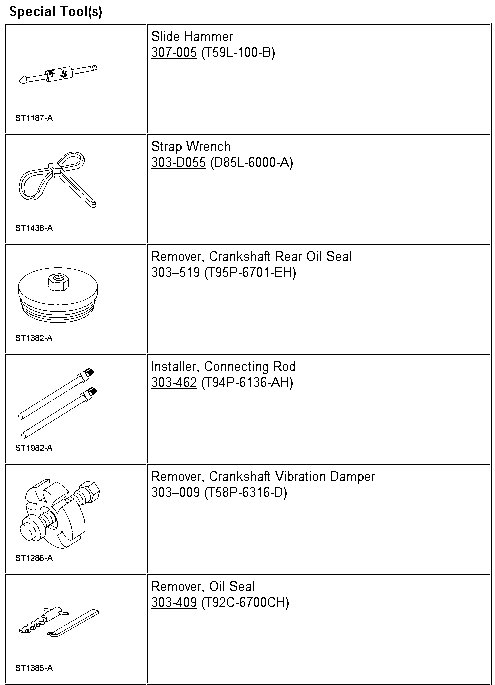
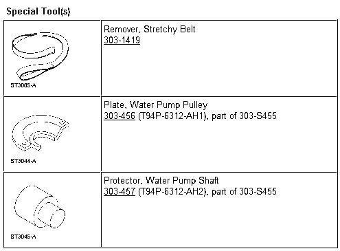

CAUTION: During engine repair procedures, cleanliness is extremely important. Any foreign material, including any material created while cleaning gasket surfaces that enters the oil passages, coolant passages or the oil pan, can cause engine failure.
NOTE: Early build vehicles are equipped with the coolant pump drive pulley on the LH intake camshaft, late build vehicles are equipped with the coolant pump drive pulley on the LH exhaust camshaft.
All vehicles
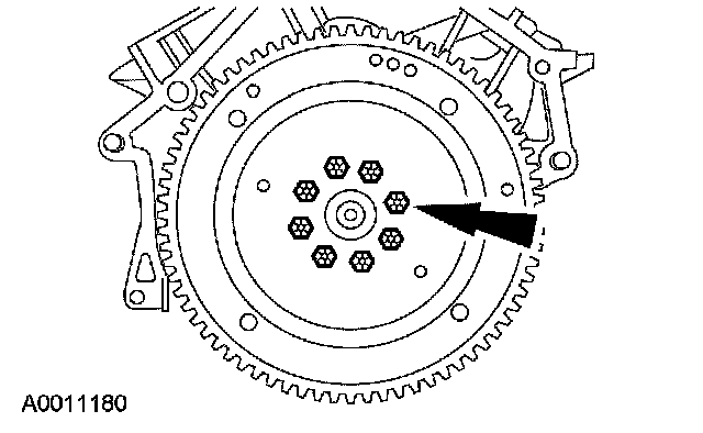
1. Remove the bolts and the flexplate.
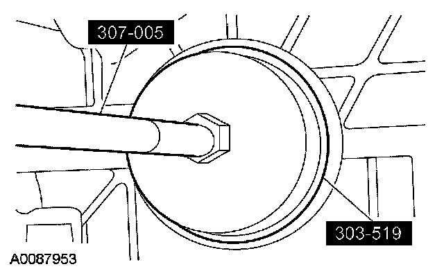
2. Using the special tools, remove and discard the crankshaft rear oil seal.
3. Mount the engine on a suitable stand.
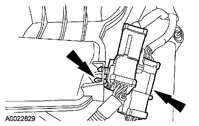
4. Detach the engine control sensor wiring connectors from the upper intake manifold.
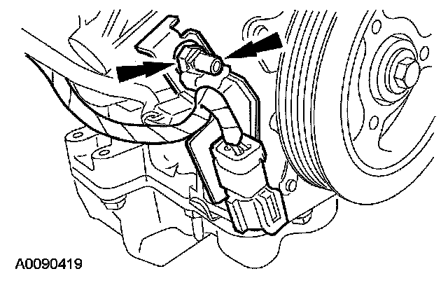
5. Detach the wiring retainer, remove the nut and the heated oxygen sensor (HO2S) electrical connector bracket.
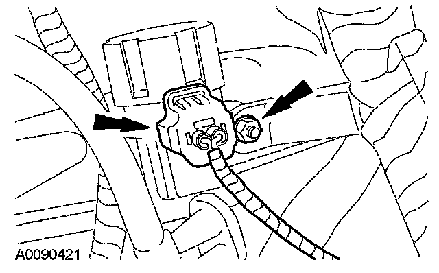
6. Disconnect the exhaust gas recirculation (EGR) vacuum regulator electrical connector and remove the nut. Detach the wiring harness retainer.
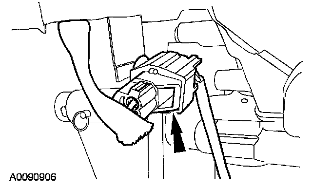
7. Disconnect the knock sensor (KS) electrical connector.
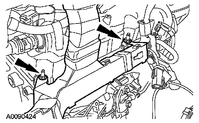
8. Remove the nuts and the engine control wire harness.
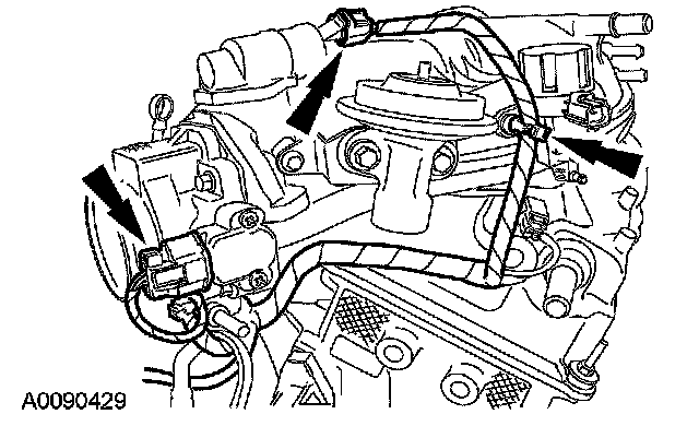
9. Disconnect the idle air control (IAC) valve and the throttle position (TP) sensor electrical connectors, and detach the wiring retainer.
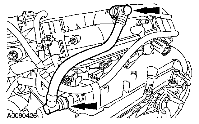
10. Remove the positive crankcase ventilation (PCV) tube.
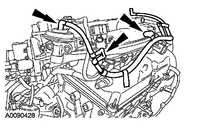
11. Disconnect the vacuum tube fittings from the EGR valve, EGR vacuum regulator and the intake manifold.

12. Disconnect the throttle body coolant hose.
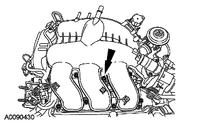
13. Remove the bolts and upper intake manifold.
^ Discard the gaskets.
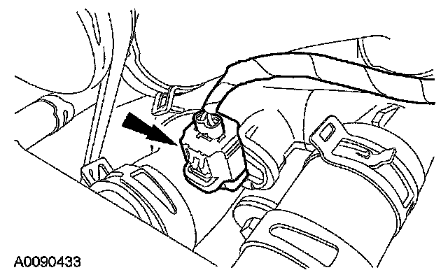
14. Disconnect the engine coolant temperature (ECT) sensor electrical connector.
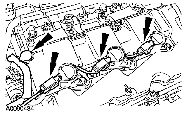
15. Disconnect the RH coil-on-plug electrical connectors and detach the wiring retainer.
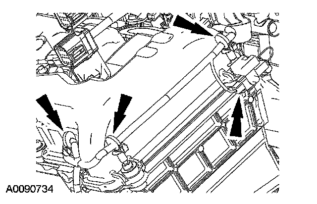
16. Disconnect the radio interference capacitor electrical connector and detach the wiring retainers.
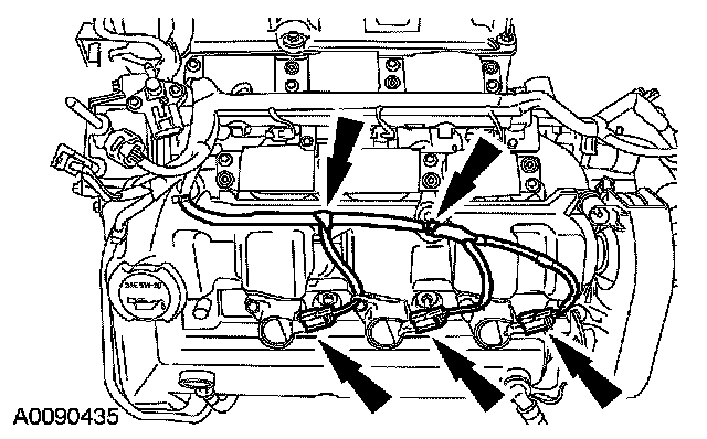
17. Disconnect the LH coil-on-plug electrical connectors and detach the wiring retainers.
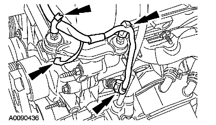
18. Disconnect the camshaft position sensor (CMP) and oil pressure sensor electrical connectors and detach the wiring retainers.
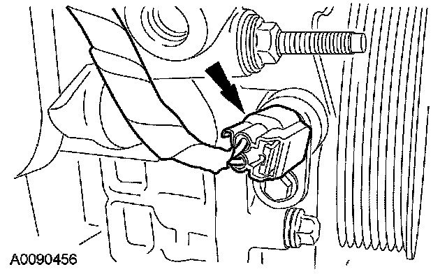
19. Disconnect the crankshaft position (CKP) sensor electrical connector and detach the wiring retainers.
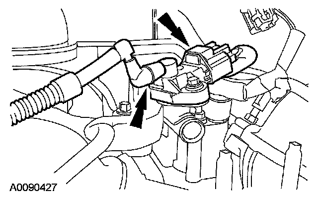
20. Disconnect the fuel rail pressure and temperature sensor electrical connector and vacuum tube.
^ Remove the engine vacuum harness.
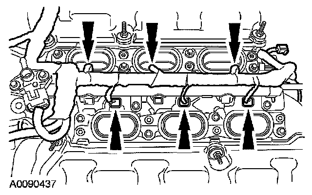
21. Disconnect the fuel injector electrical connectors and remove the fuel charging wiring harness.
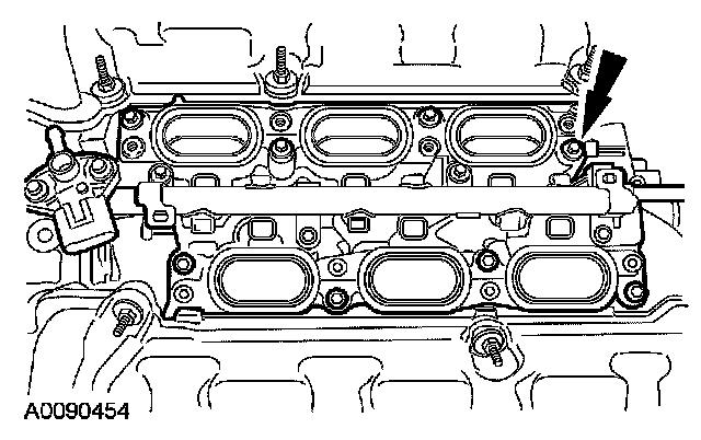
22. Remove the bolts and the lower intake manifold.
^ Discard the gaskets.
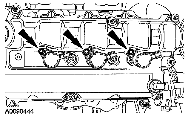
23. CAUTION: When removing the coil-on-plugs, a slight twisting motion will break the seal and ease removal.
NOTE: LH shown, RH similar.
Remove the bolts and the 6 coil-on-plugs.
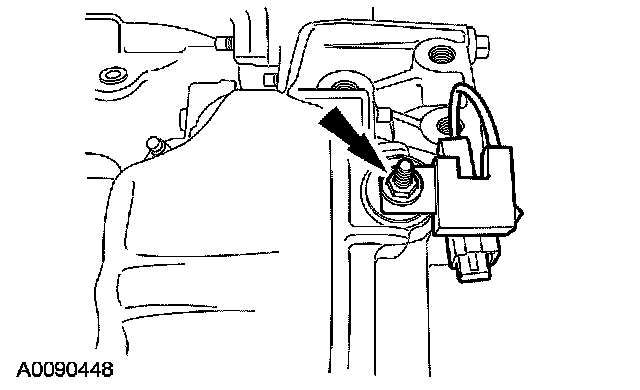
24. Remove the nut and the radio interference capacitor.
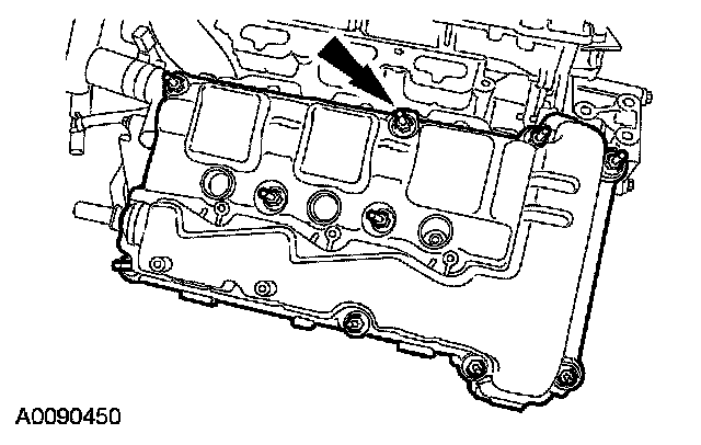
25. Remove the bolts and the RH valve cover.
^ Discard the gasket.
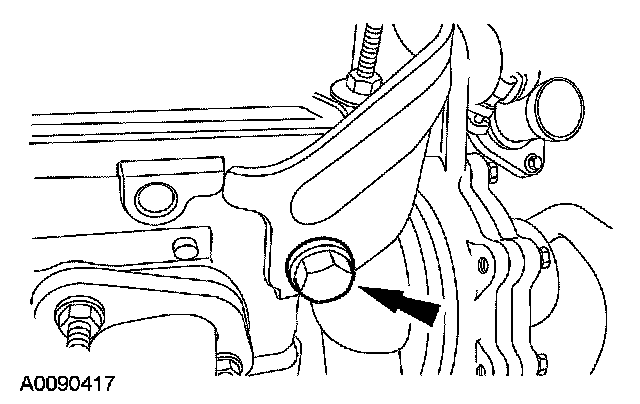
26. If equipped, remove the bolt and the engine lift bracket.
Early build vehicles
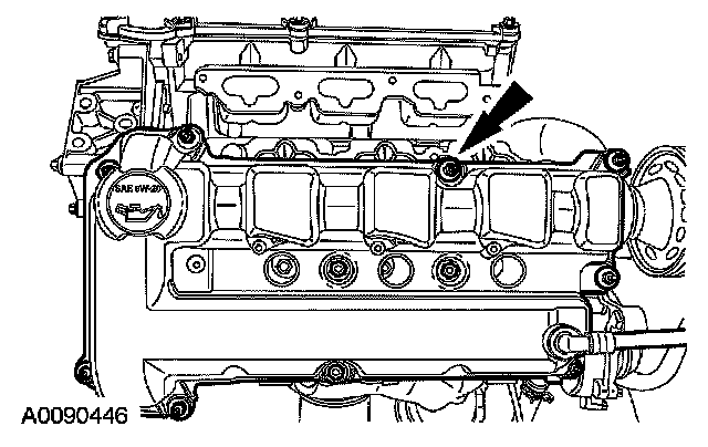
27. Remove the bolts and the LH valve cover.
^ Discard the gasket.
Late build vehicles
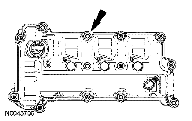
28. Remove the bolts and the LH valve cover.
^ Discard the gasket.
4x2 vehicles
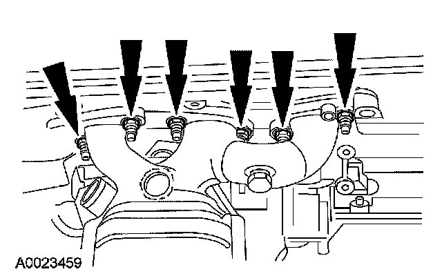
29. Remove the nuts, the RH exhaust manifold and the gasket.
^ Discard the gasket and nuts.
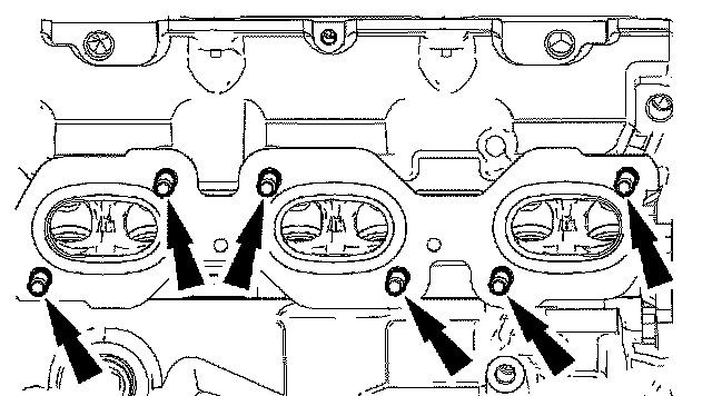
30. Remove and discard the 6 RH exhaust manifold studs.
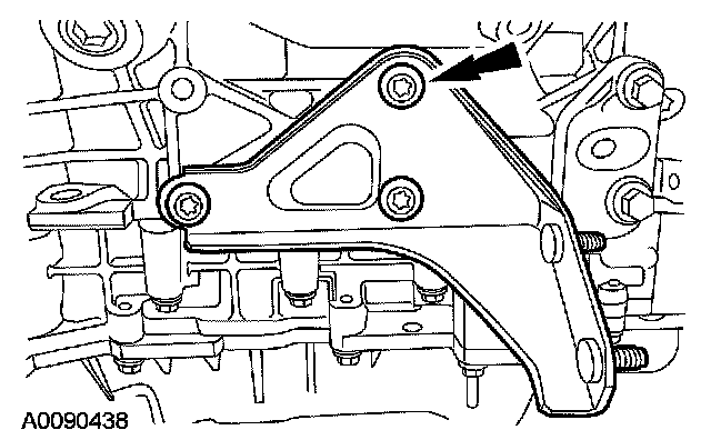
31. Remove the bolts and the halfshaft support bracket.
All vehicles
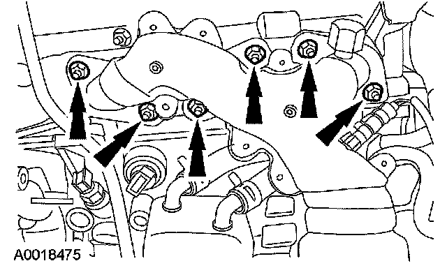
32. Remove the nuts, the LH exhaust manifold and the gasket.
^ Discard the gasket and nuts.
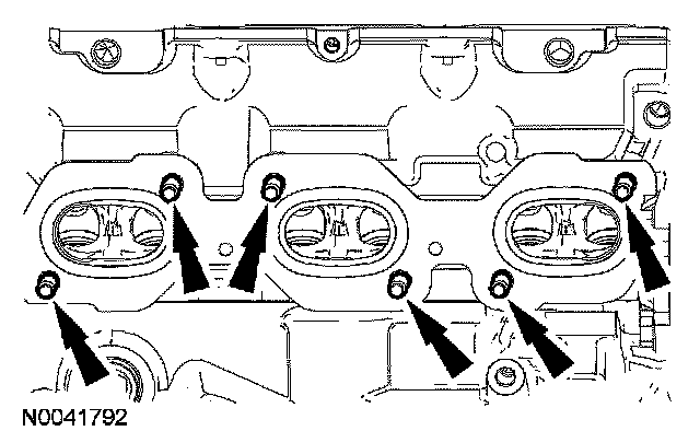
33. Remove and discard the 6 LH exhaust manifold studs.
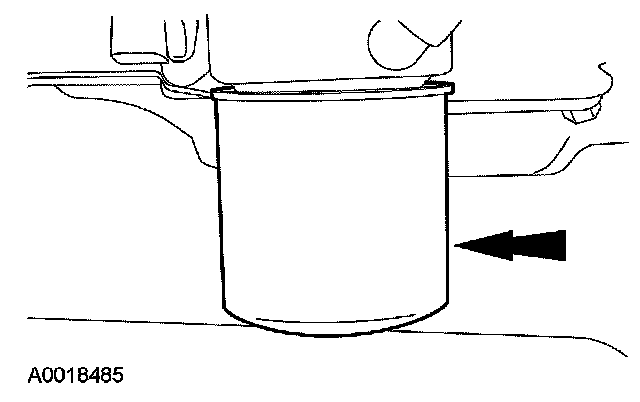
34. Remove and discard the oil filter.
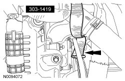
35. Position the Stretchy Belt Remover under the coolant pump belt as shown.
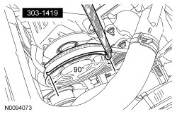
36. NOTE: Feed the Stretchy Belt Remover onto the camshaft coolant pump pulley approximately 90 degrees.

Turn the crankshaft clockwise and feed the Stretchy Belt Remover evenly on the camshaft coolant pump pulley as shown.
37. Remove the coolant pump belt.
^ Fold the Stretchy Belt Remover over the top of the coolant pump belt.
^ In one quick motion, pull the Stretchy Belt Remover up and toward the front of the engine, removing the coolant pump belt
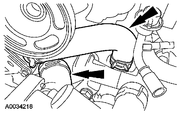
38. Disconnect the hoses.
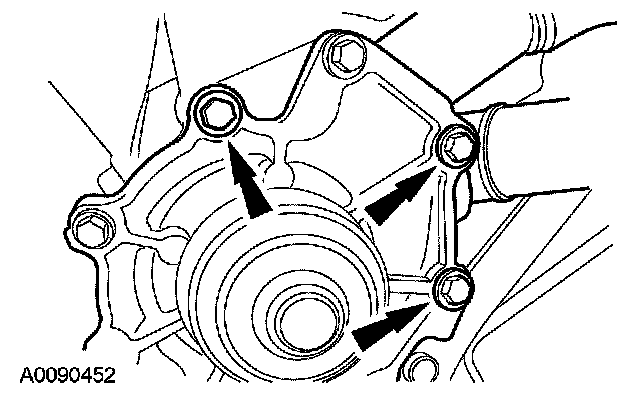
39. Remove the 3 bolts and the coolant pump.
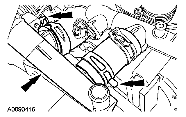
40. Disconnect the hoses and remove the coolant tube.
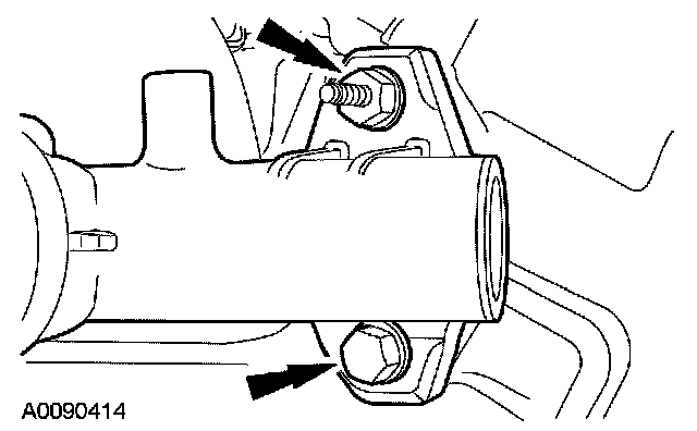
41. Remove the nut, bolt and the coolant bypass tube.
Factory Service Tools
Use the Manual With the Right Hardware
Pair factory procedures with proven DIY tools so the instructions are easier to execute.
Disclosure: Verified tool recommendations may earn an affiliate commission at no cost to you.
When to See a Mechanic
Stop DIY work and contact a certified mechanic immediately if any of the following apply:
- • You smell fuel, burning insulation, or see smoke.
- • Brakes feel soft, pull hard to one side, or make grinding noises.
- • The engine overheats, stalls repeatedly, or misfires under load.
- • You are missing required tools, torque specs, or safe lifting equipment.
- • You are not confident in the next step or safety outcome.
Rather have a pro handle this?
A certified mobile mechanic comes to your home or office. They bring the tools, you stay comfortable. No tow truck, no waiting room, no surprises.
Comes to youSame-day available12-month warranty
Get a Free QuoteNo obligation. See pricing before you book.