
Safety Warning
DIY auto repair can cause serious injury, fire, or vehicle damage. These guides are for informational purposes only. Always follow OEM torque specs, wear PPE, and consult a certified mechanic if you are unsure. You are solely responsible for your safety.
2012 Mazda Mazdaspeed3 L4-2.3L TurboFACTORY OEM SERVICE PROCEDURE
Crankshaft Position Sensor: Service and Repair
CRANKSHAFT POSITION (CKP) SENSOR REMOVAL/INSTALLATION [MZR 2.3 DISI Turbo]
Removal
CAUTION:
- When foreign material such as an iron chip is on the CKP sensor, it can cause abnormal output from the sensor because of flux turbulence and adversely affect the engine control. Be sure there is no foreign material on the CKP sensor when replacing.
- Do not assemble the CKP sensor or change the installation position using any method other than the following. Otherwise, it could negatively affect engine controls, such as the ignition timing and fuel injection.
1. Remove the battery cover. Removal and Replacement
2. Disconnect the negative battery cable. Removal and Replacement
3. Perform the following procedure for easier access.
a. Remove the aerodynamic under cover No.2. Aerodynamic Under Cover No. 2 Removal/Installation
b. Remove the front splash shield (RH). Splash Shield Removal/Installation
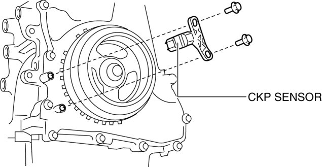
4. Disconnect the CKP sensor connector.
5. Remove the CKP sensor.
Installation
CAUTION:
- When foreign material such as an iron chip is on the CKP sensor, it can cause abnormal output from the sensor because of flux turbulence and adversely affect the engine control. Be sure there is no foreign material on the CKP sensor when replacing.
- Do not assemble the CKP sensor or change the installation position using any method other than the following. Otherwise, it could negatively affect engine controls, such as the ignition timing and fuel injection.
1. Perform the following procedure so that piston No.1 is at TDC.
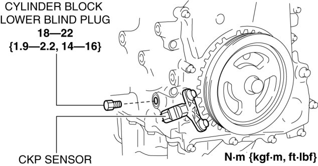
a. Rotate the crankshaft in the direction of the engine rotation and remove the cylinder block lower blind plug when the No.1 cylinder is at the point prior to TDC of compression, then install the SST.
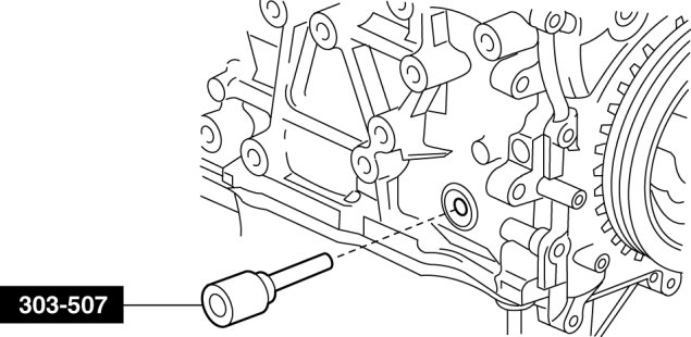
b. Rotate the crankshaft in the direction of the engine rotation so that the No.1 piston is at TDC of the compression stroke. (Until the crank weight contacts SST and stops.)
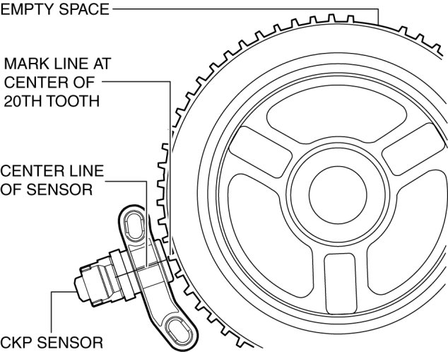
2. Using a straight edge, draw a straight line directly in the center of the twentieth tooth of the crankshaft pulley pulse wheel (counting counterclockwise from the empty space).
CAUTION:
- If the line is not accurately drawn, ignition timing, fuel injection and other engine control systems will be adversely effected. Draw the straight line carefully using a straight edge.
3. Align the center line of the crankshaft position sensor and the line drawn in Step 2, then install the sensor.
4. Install the CKP sensor fitting bolts.
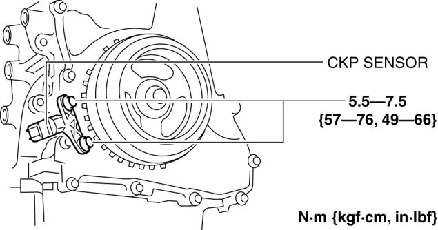
5. Remove the SST then install the cylinder block lower blind plug.
Factory Service Tools
Use the Manual With the Right Hardware
Pair factory procedures with proven DIY tools so the instructions are easier to execute.
Disclosure: Verified tool recommendations may earn an affiliate commission at no cost to you.
When to See a Mechanic
Stop DIY work and contact a certified mechanic immediately if any of the following apply:
- • You smell fuel, burning insulation, or see smoke.
- • Brakes feel soft, pull hard to one side, or make grinding noises.
- • The engine overheats, stalls repeatedly, or misfires under load.
- • You are missing required tools, torque specs, or safe lifting equipment.
- • You are not confident in the next step or safety outcome.