
Safety Warning
DIY auto repair can cause serious injury, fire, or vehicle damage. These guides are for informational purposes only. Always follow OEM torque specs, wear PPE, and consult a certified mechanic if you are unsure. You are solely responsible for your safety.
2012 Mazda 6 V6-3.7LFACTORY OEM SERVICE PROCEDURE
Component Tests and General Diagnostics
BODY CONTROL MODULE (BCM) INSPECTION
1. Remove the front scuff plate. (driver-side) Front Scuff Plate Removal/Installation
2. Remove the front side trim. (driver-side) Front Side Trim Removal/Installation
3. Remove the BCM with the connector connected. Service and Repair
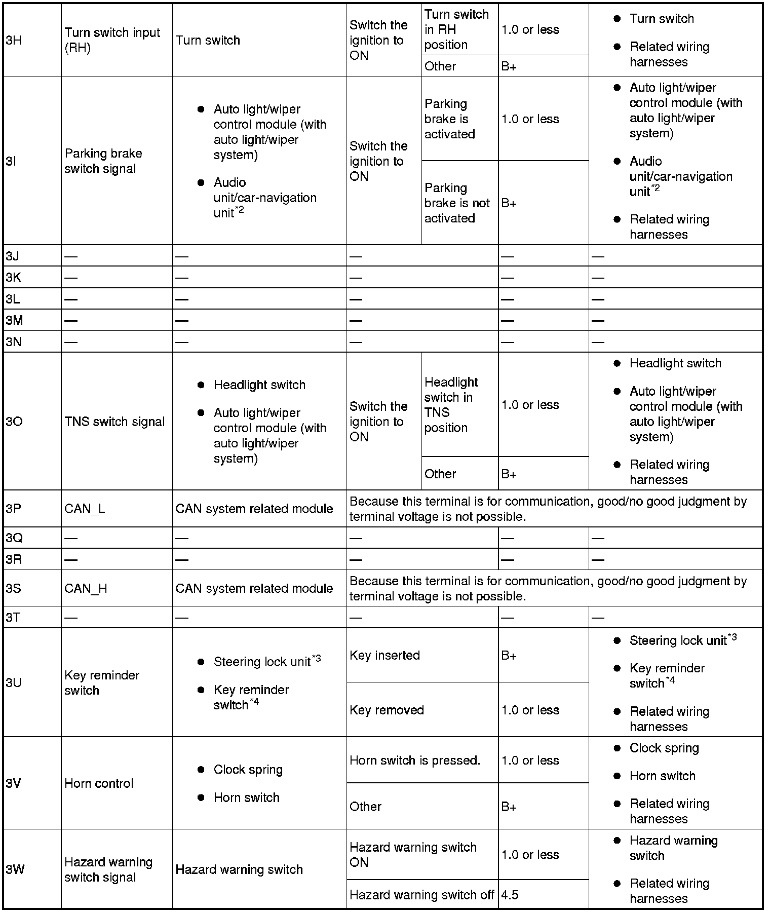
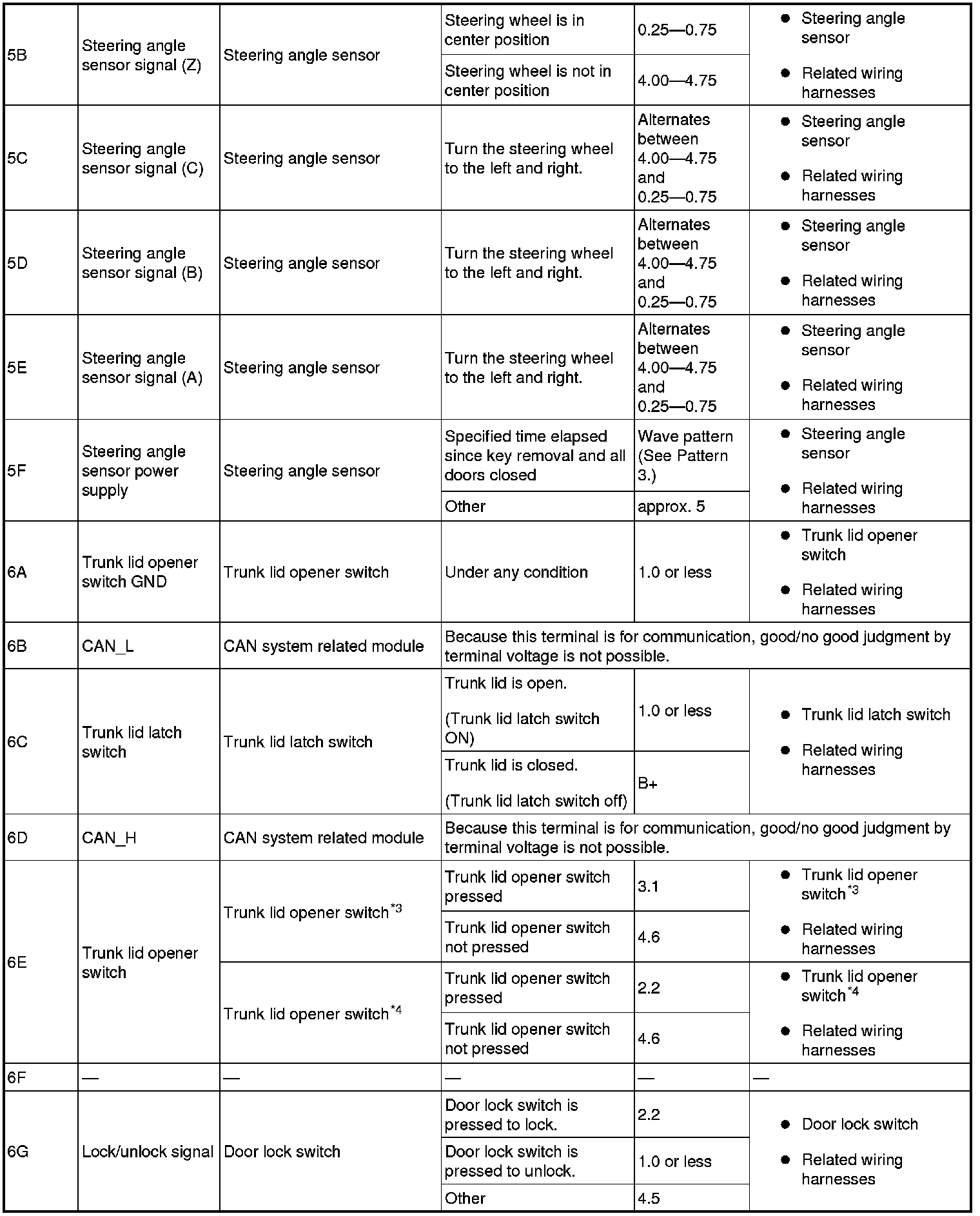
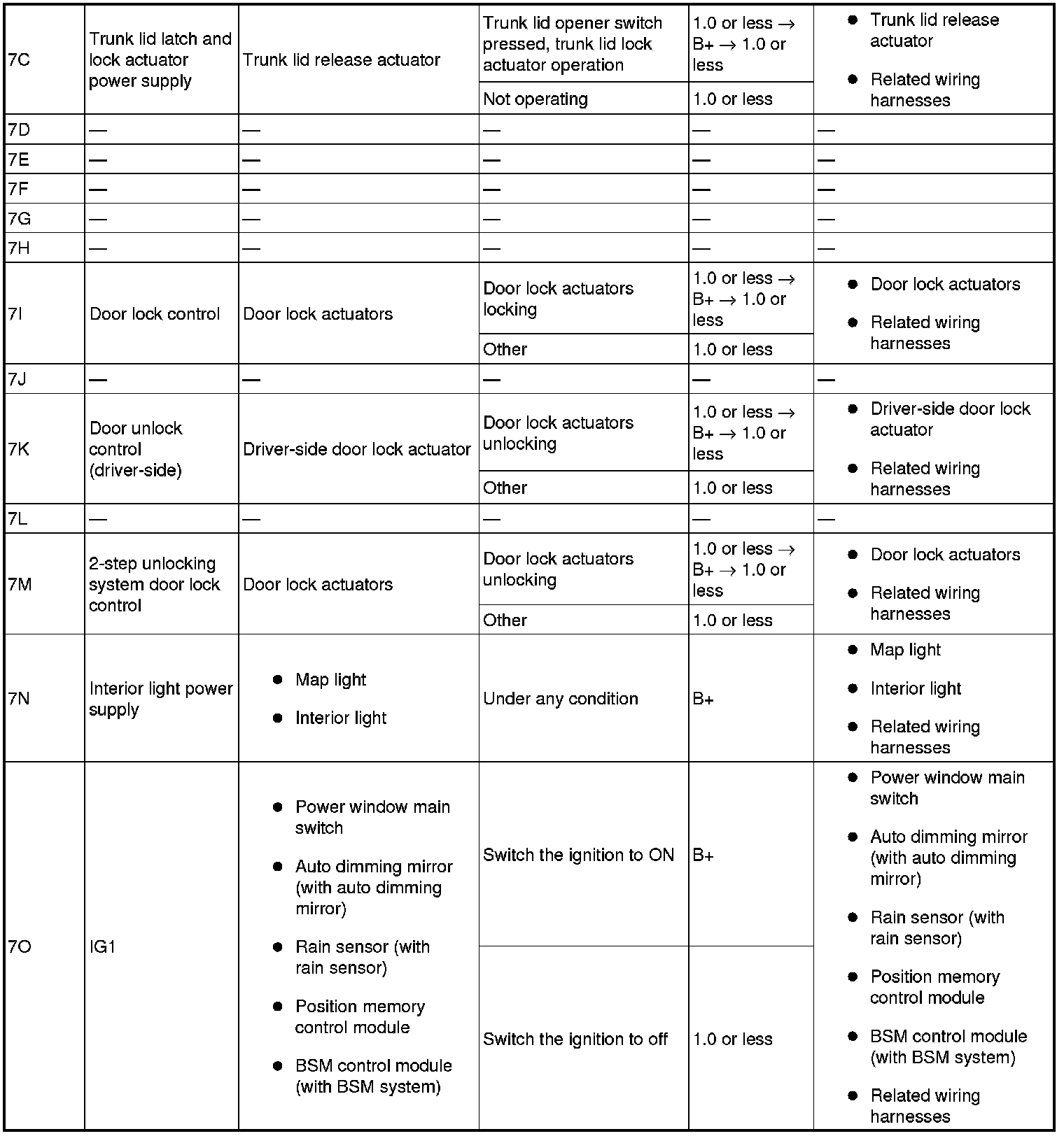
4. Measure the voltage at each terminal is as indicated in the Terminal Voltage Tables.
- If the voltage is not as specified in the Terminal Voltage Table, inspect the parts under "Inspection item (s)".
- If the system does not work properly even though the parts or related wiring harnesses do not have any malfunction, replace the BCM.
Terminal Voltage Table (Reference)






*1
With theft-deterrent system
*2
With car-navigation system
*3
With advanced keyless entry and push button start system
*4
Without advanced keyless entry and push button start system
Generated pulse (reference)
Pattern 1
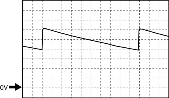
- Terminal: 8G (+) -> body ground (-)
- Oscilloscope setting: 2 V/DIV (Y), 1 ms/DIV (X), DC range
Pattern 2
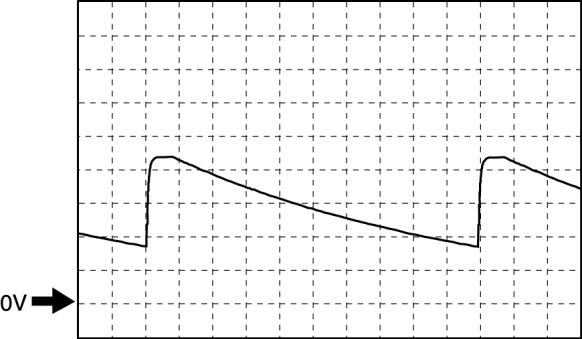
- Terminal:
- Bonnet latch switch signal: 1S (+) -> body ground (-)
- Front door latch switch (driver side) input signal: 8B (+) -> body ground (-)
- Lock/unlock input: 8C (+) -> body ground (-)
- Front door latch switch (passenger side) signal: 8D (+) -> body ground (-)
- Unlock input (Driver-side door lock-link switch): 8E (+) -> body ground (-)
- Rear door switch (RH) signal: 8F (+) -> body ground (-)
- Lock input (Driver-side door lock-link switch): 8G (+) -> body ground (-)
- Rear door switch (LH) signal: 8H (+) -> body ground (-)
- Oscilloscope setting: 1 V/DIV (Y), 1 ms/DIV (X), DC range
Pattern 3

- Terminal: 5F (+) -> body ground (-)
- Oscilloscope setting: 1 V/DIV (Y), 200 Microsecond/DIV (X), DC range
Pattern 4

- Terminal:
- Interior light control: 6M (+) -> body ground (-)
- Courtesy light control: 6O (+) -> body ground (-)
- Trunk room light control: 7B (+) -> body ground (-)
- Oscilloscope setting: 5 V/DIV (Y), 5 ms/DIV (X), DC range
Factory Service Tools
Use the Manual With the Right Hardware
Pair factory procedures with proven DIY tools so the instructions are easier to execute.
Disclosure: Verified tool recommendations may earn an affiliate commission at no cost to you.
When to See a Mechanic
Stop DIY work and contact a certified mechanic immediately if any of the following apply:
- • You smell fuel, burning insulation, or see smoke.
- • Brakes feel soft, pull hard to one side, or make grinding noises.
- • The engine overheats, stalls repeatedly, or misfires under load.
- • You are missing required tools, torque specs, or safe lifting equipment.
- • You are not confident in the next step or safety outcome.
Rather have a pro handle this?
A certified mobile mechanic comes to your home or office. They bring the tools, you stay comfortable. No tow truck, no waiting room, no surprises.
Comes to youSame-day available12-month warranty
Get a Free QuoteNo obligation. See pricing before you book.