
Safety Warning
DIY auto repair can cause serious injury, fire, or vehicle damage. These guides are for informational purposes only. Always follow OEM torque specs, wear PPE, and consult a certified mechanic if you are unsure. You are solely responsible for your safety.
2012 Mazda 6 L4-2.5LFACTORY OEM SERVICE PROCEDURE
Component Tests and General Diagnostics
PCM INSPECTION [MZR 2.5]
Using M-MDS
NOTE:
- PIDs for the following parts are not available on this model. Go to the appropriate part inspection.
- CMP sensor
- Main relay
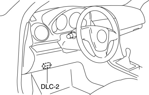
1. Connect the M-MDS to the DLC-2.
2. Switch the ignition to ON.
3. Measure the PID value.
- If PID value is not within the specification, follow the instructions in Action column.
NOTE:
- The PID/DATA MONITOR function monitors the calculated value of the input/output signals in the PCM. Therefore, an output device malfunction is not directly indicated as a malfunction of the monitored value for the output device. If a monitored value of an output device is out of specification, inspect the monitored value of the input device related to the output control.
- For input/output signals except those of the monitoring items, use a voltmeter to measure the PCM terminal voltage.
- The simulation items that are used in the ENGINE CONTROL SYSTEM OPERATION INSPECTION are as follows.
- ACCS, ALTF, ARPMDES, EVAPCP, EVAPCV, FAN_DUTY, FP, HTR11, IMRC, IMTV, INJ_1~4, SEGRP, Test, VT Duty1 wt
PID/DATA monitor table (reference)

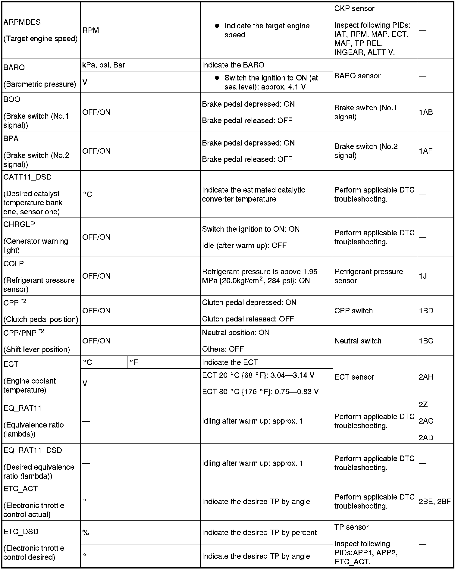
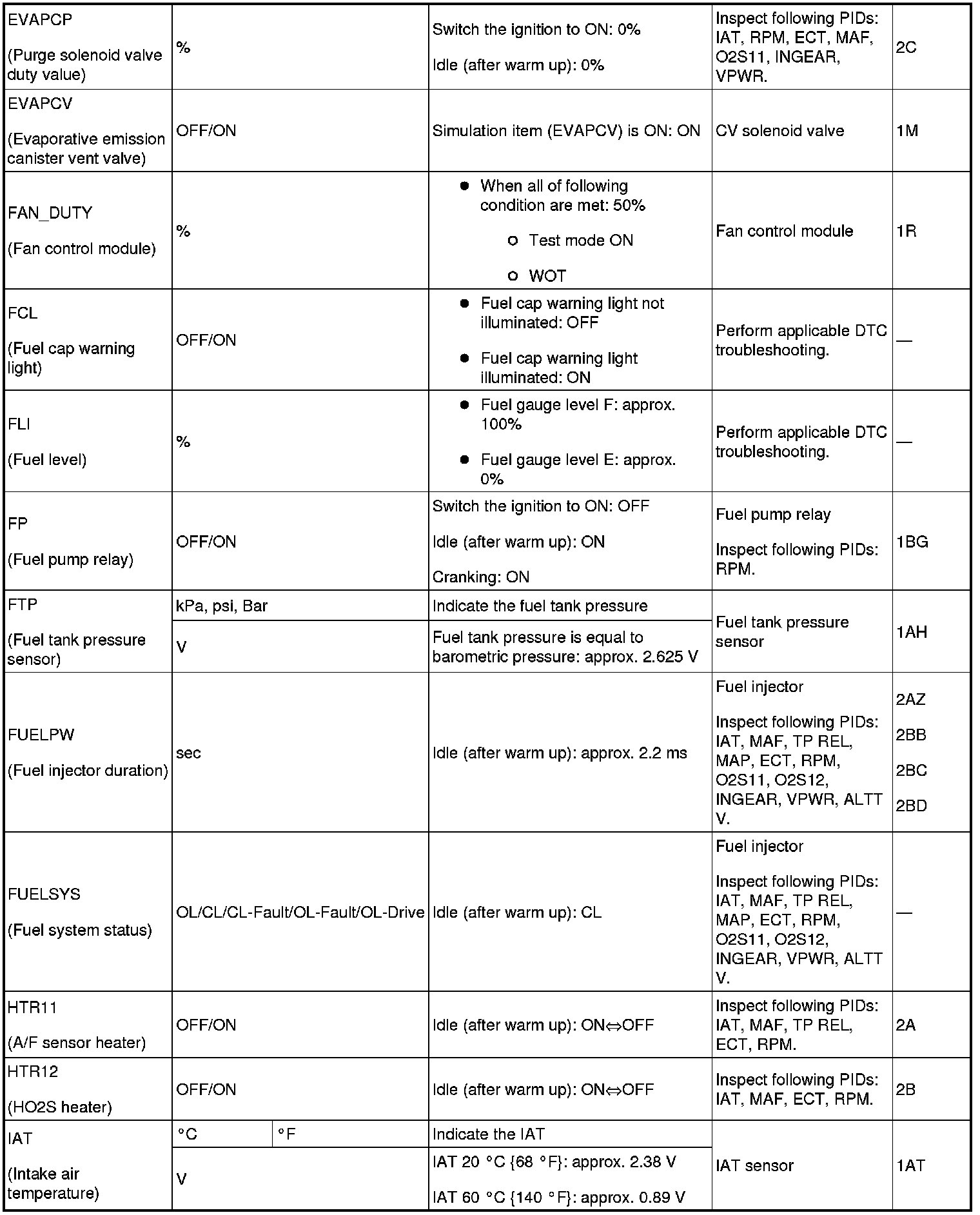
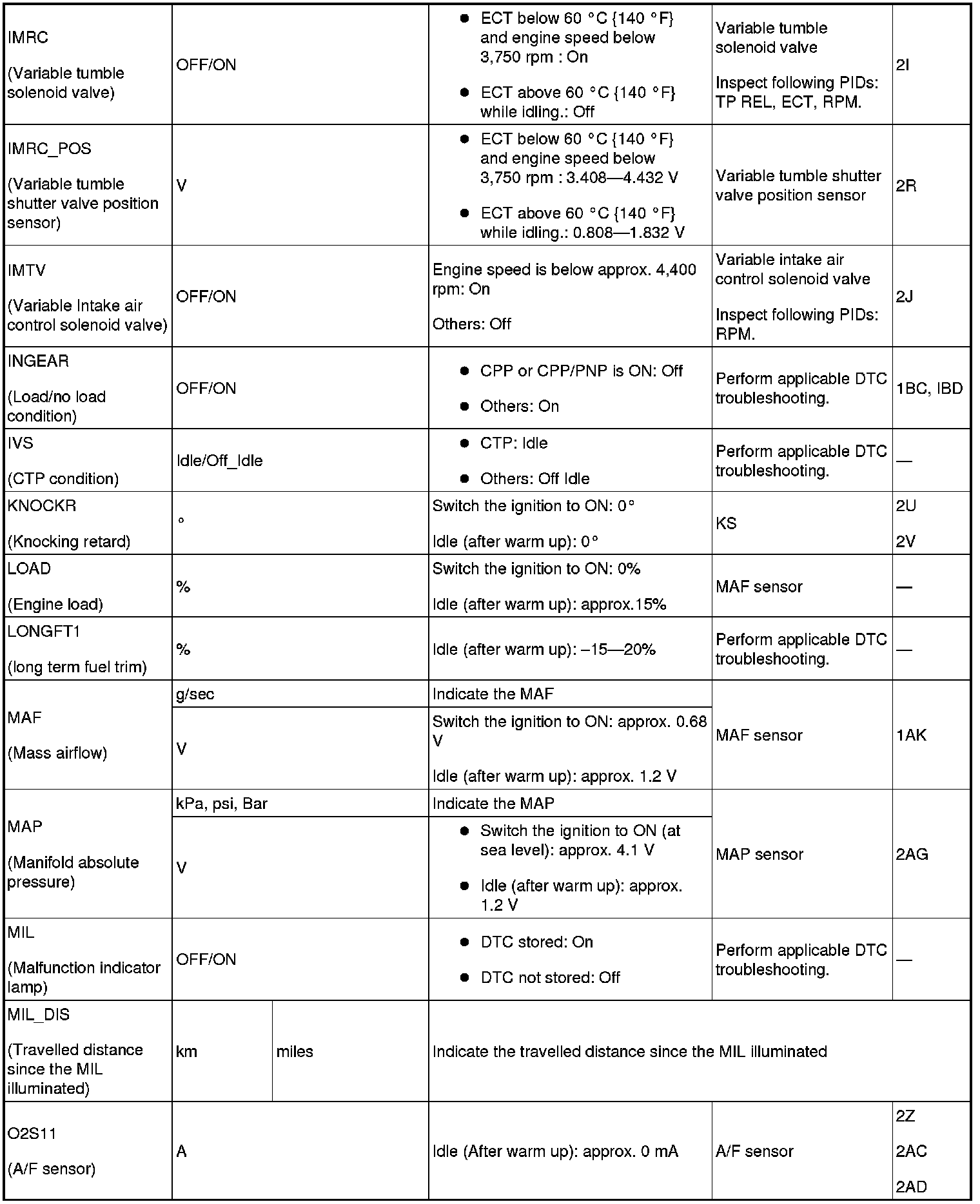
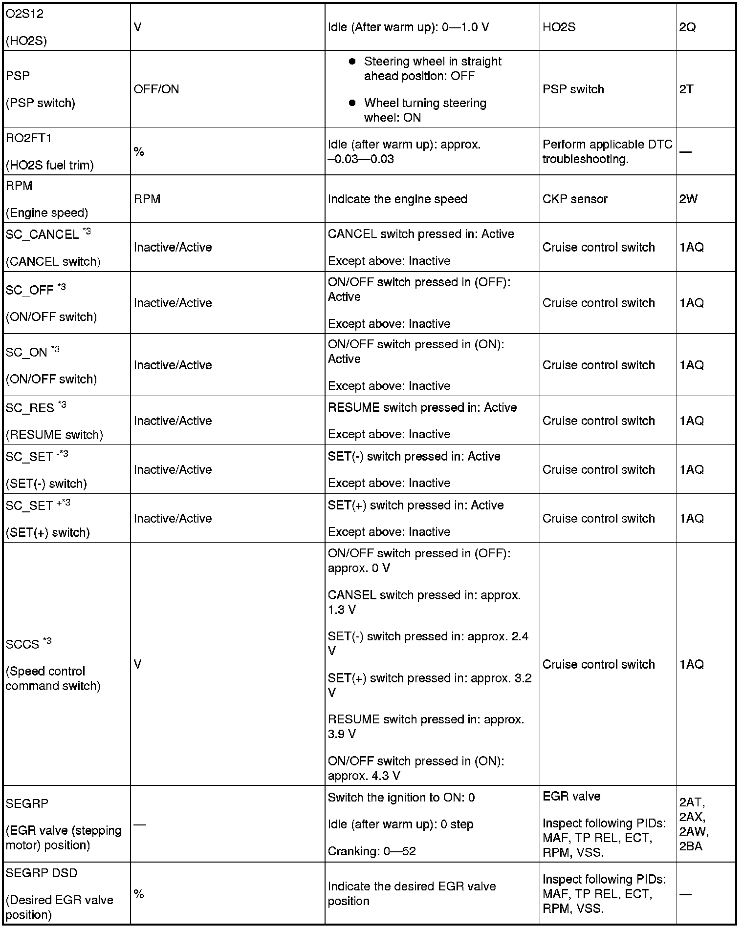


*1
Calculated value; differs from terminal voltage
*2
MTX
*3
Vehicles equipped with cruise control switch
- Following PIDs are for the ATX models. If inspects for following PIDs, PID/Data Monitor Inspection
Without Using the SST
CAUTION:
- The PCM terminal voltages vary with change in measuring conditions and vehicle conditions. Always carry out a total inspection of the input systems, output systems, and PCM to determine the cause of trouble. Otherwise, a wrong diagnosis will be made.
1. Measure the voltage at each terminal.
- If any incorrect voltage is detected, inspect the related system(s), wiring harnesses and connector(s) referring to the Action column in the terminal voltage table.
Terminal voltage table (Reference)
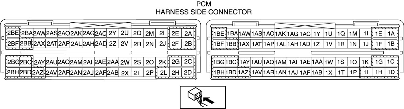
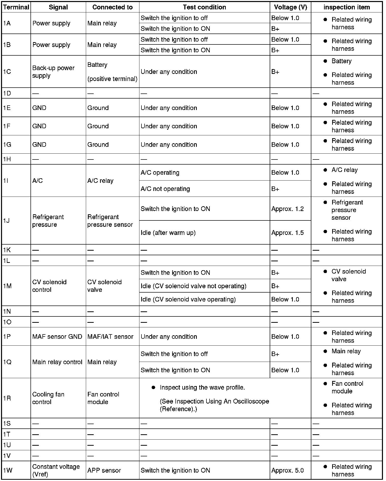
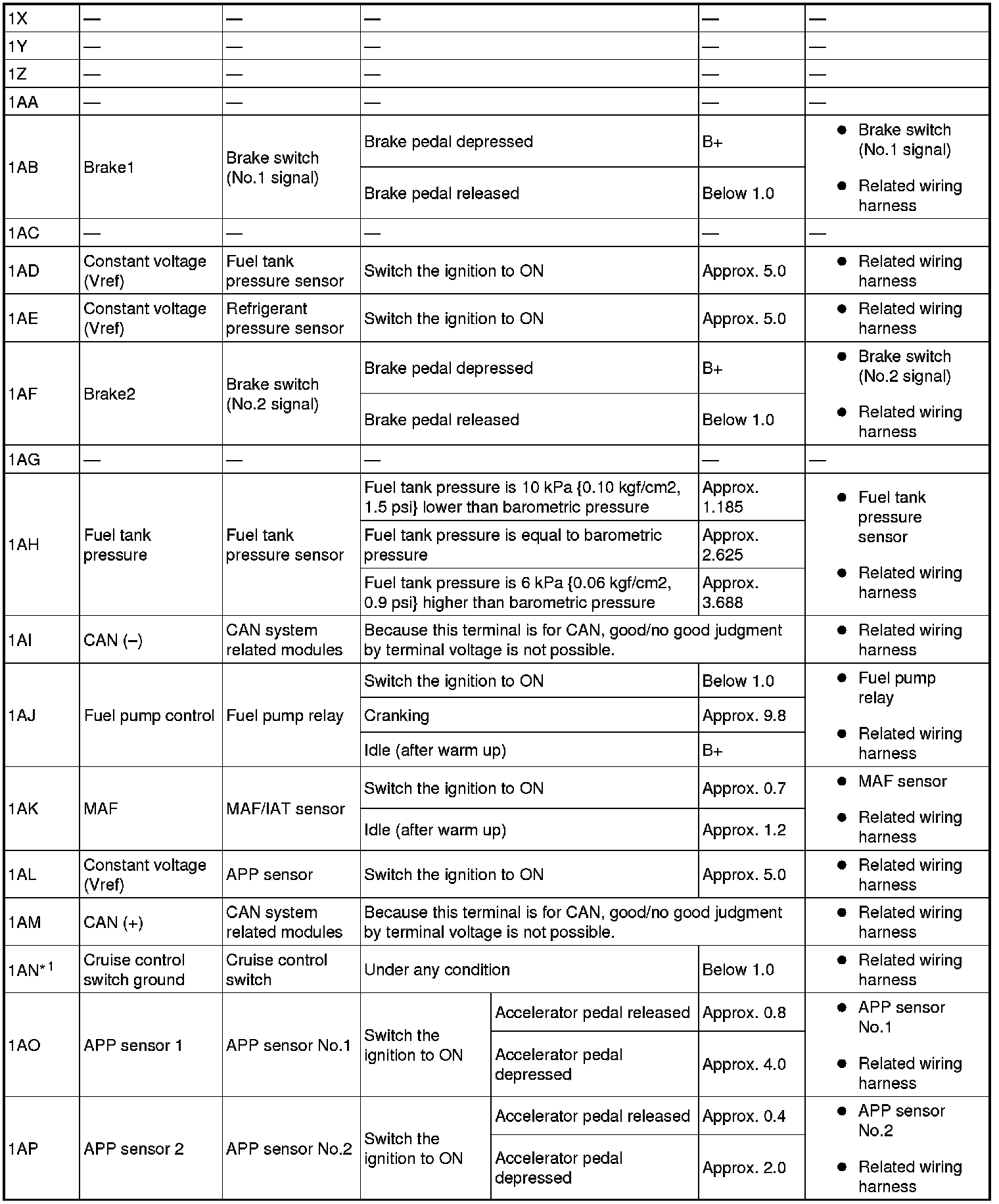

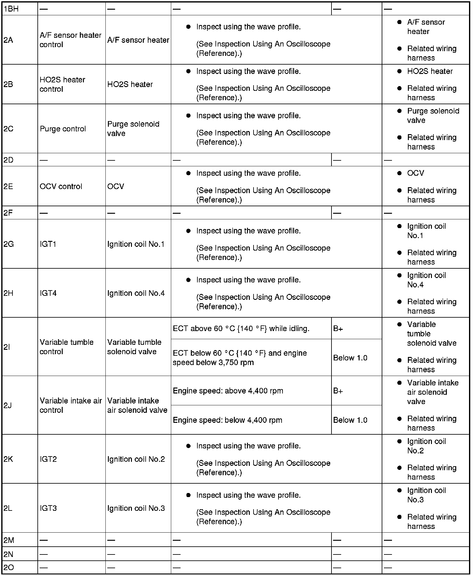
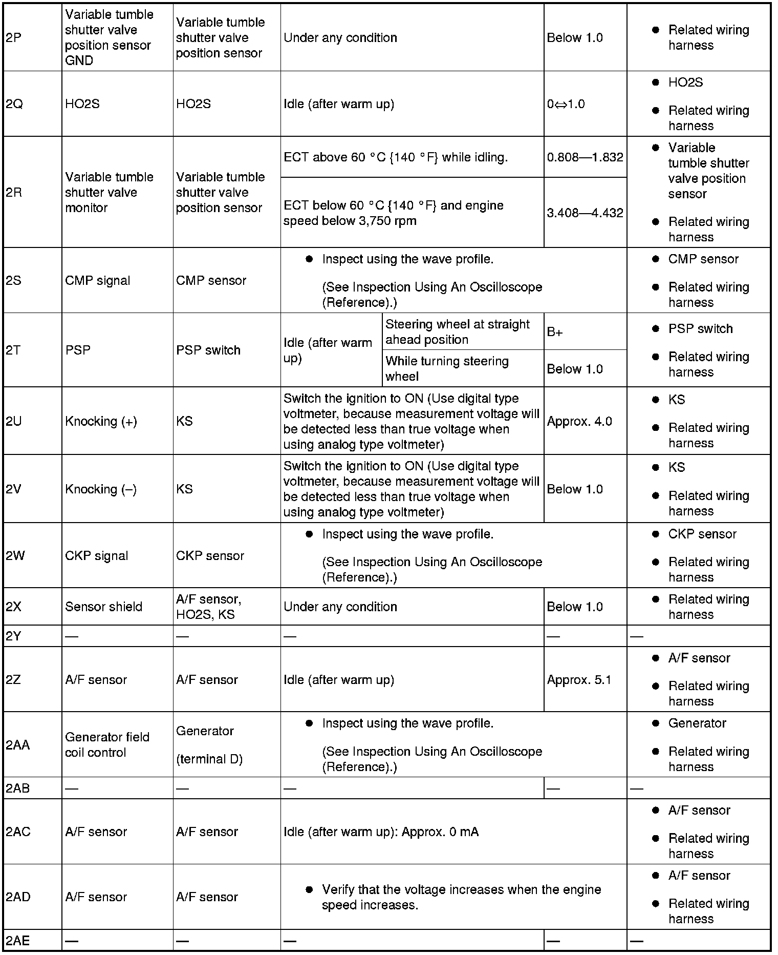
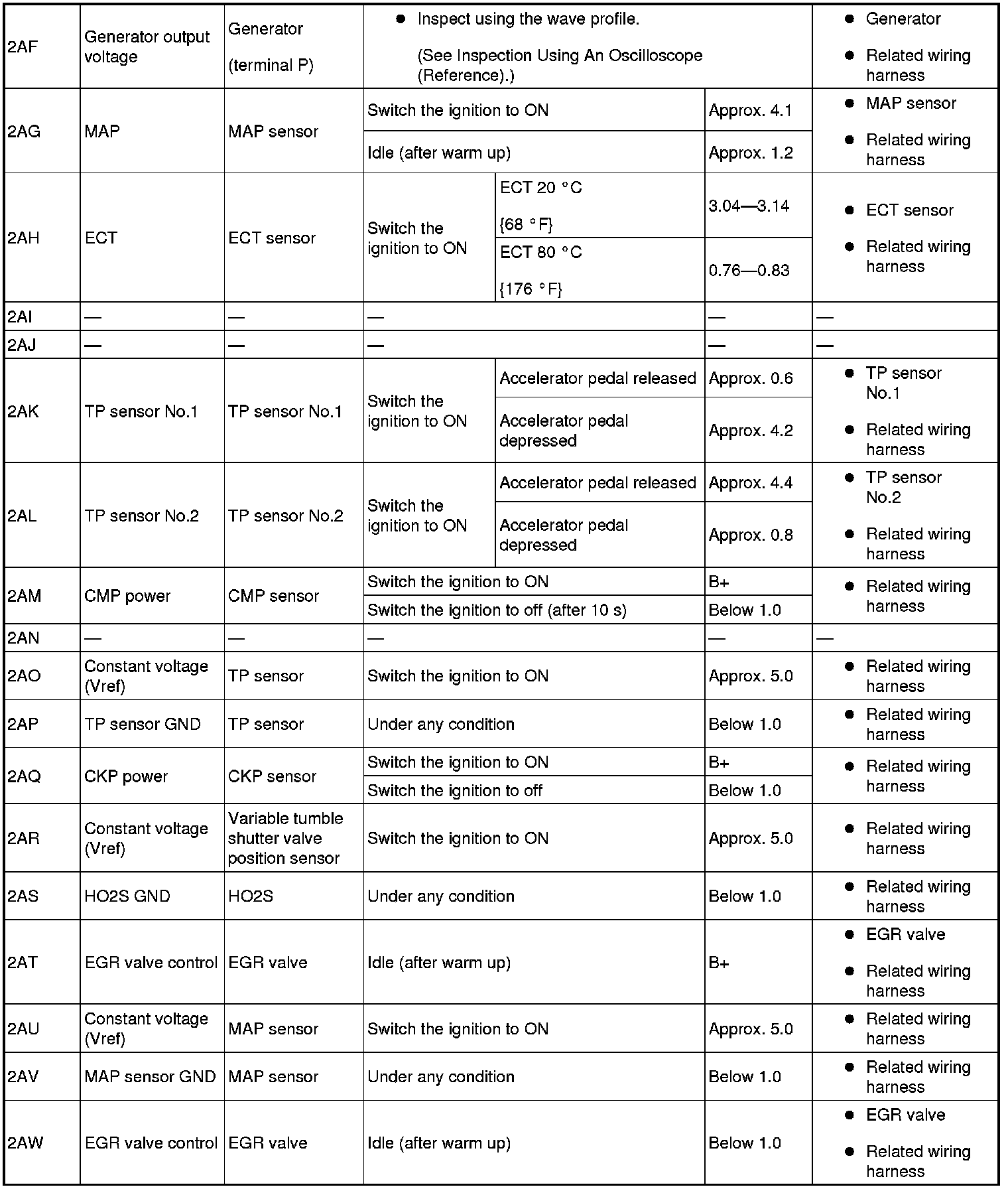
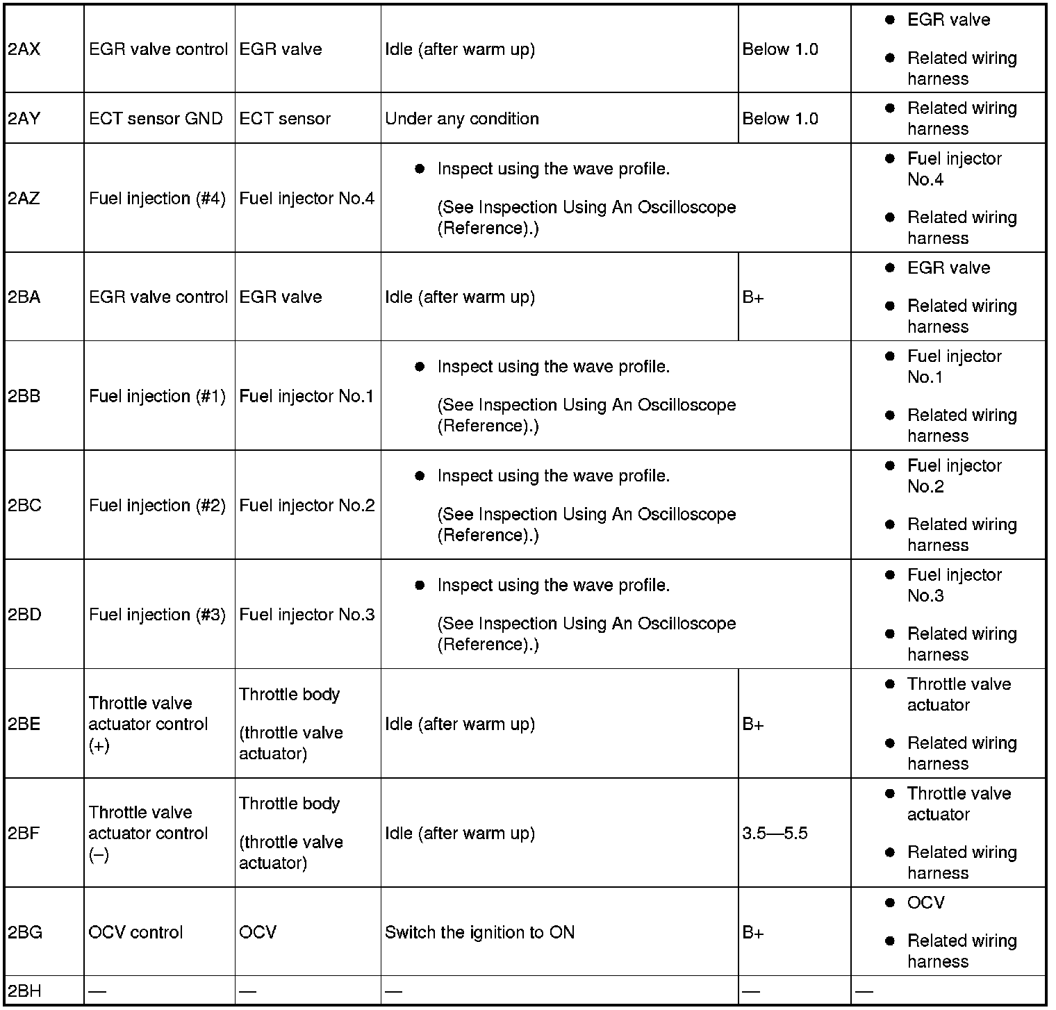
*1
Vehicles equipped with cruise control switch
*2
Without advanced keyless entry and push button start system
*3
With advanced keyless entry and push button start system
*4
MTX
*5
ATX
Inspection Using An Oscilloscope (Reference)
Fan control module signal
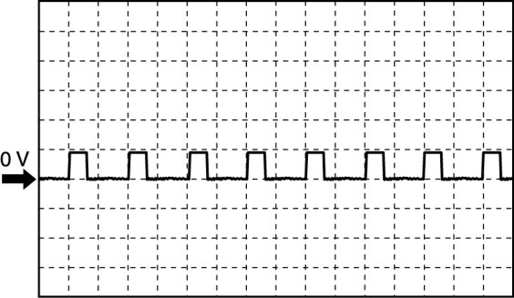
PCM terminals
- 1R-body ground(-)
Oscilloscope setting
- 5 V/DIV (Y), 20 ms/DIV (X), DC range
Vehicle condition
- Idle (after warm up)
A/F sensor heater control
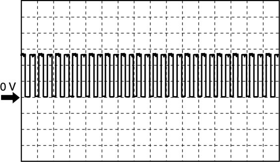
PCM terminals
- 2A(+)-body ground(-)
Oscilloscope setting
- 5 V/DIV (Y), 200 ms/DIV (X), DC range
Vehicle condition
- Idle (immediately after starting the engine)
HO2S heater control

PCM terminals
- 2B(+)-body ground(-)
Oscilloscope setting
- 5 V/DIV (Y), 1 s/DIV (X), DC range
Vehicle condition
- Idle (immediately after starting the engine)
Purge control signal
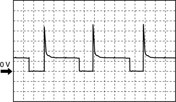
PCM terminals
- 2C(+)-body ground(-)
Oscilloscope setting
- 10 V/DIV (Y), 20 ms/DIV (X), DC range
Vehicle condition
- Idle (after warm up)
OCV control signal
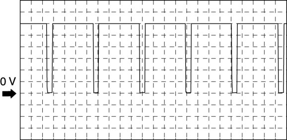
PCM terminals
- 2E(+)-body ground(-)
Oscilloscope setting
- 2 V/DIV (Y), 0.8 ms/DIV (X), DC range
Vehicle condition
- Idle (after warm up)
CMP sensor signal
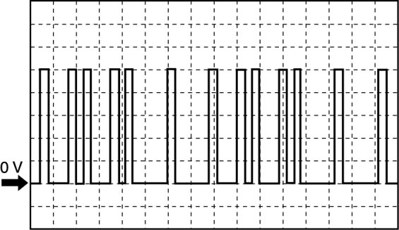
PCM terminals
- 2S(+)-body ground(-)
Oscilloscope setting
- 1 V/DIV (Y), 25 ms/DIV (X), DC range
Vehicle condition
- Idle (after warm up)
CKP sensor signal
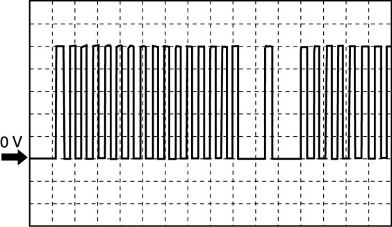
PCM terminals
- 2W(+)-body ground(-)
Oscilloscope setting
- 1 V/DIV (Y), 5 ms/DIV (X), DC range
Vehicle condition
- Idle (after warm up)
IGT1, IGT2, IGT3, IGT4 control signals
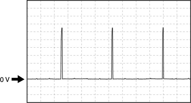
PCM terminals
- IGT1(ignition coil No.1): 2G(+)-body ground(-)
- IGT2(ignition coil No.2): 2K(+)-body ground(-)
- IGT3(ignition coil No.3): 2L(+)-body ground(-)
- IGT4(ignition coil No.4): 2H(+)-body ground(-)
Oscilloscope setting
- 1 V/DIV (Y), 50 ms/DIV (X), DC range
Vehicle condition
- Idle (after warm up)
Generator field coil control signal
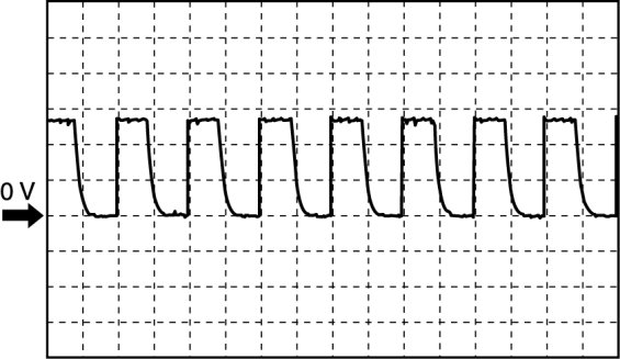
PCM terminals
- 2AA(+)-body ground(-)
Oscilloscope setting
- 0.5 V/DIV (Y), 2 ms/DIV (X), DC range
Vehicle condition
- Idle (after warm up)
Generator output voltage signal
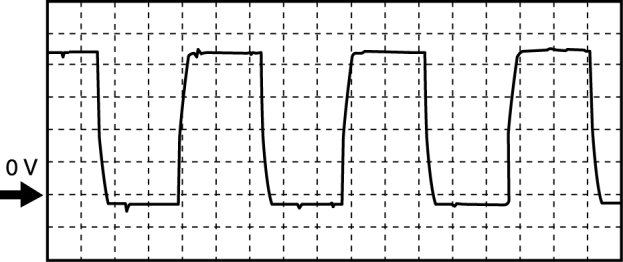
PCM terminals
- 2AF(+)-body ground(-)
Oscilloscope setting
- 2 V/DIV (Y), 2 ms/DIV (X), DC range
Vehicle condition
- Idle (after warm up)
Fuel injection control
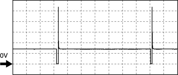
PCM terminals
- Fuel Injection No.1: 2BB(+)-body ground(-)
- Fuel Injection No.2: 2BC(+)-body ground(-)
- Fuel Injection No.3: 2BD(+)-body ground(-)
- Fuel Injection No.4: 2AZ(+)-body ground(-)
Oscilloscope setting
- 10 V/DIV (Y), 25 ms/DIV (X), DC range
Vehicle condition
- Idle (after warm up)
Factory Service Tools
Use the Manual With the Right Hardware
Pair factory procedures with proven DIY tools so the instructions are easier to execute.
Disclosure: Verified tool recommendations may earn an affiliate commission at no cost to you.
When to See a Mechanic
Stop DIY work and contact a certified mechanic immediately if any of the following apply:
- • You smell fuel, burning insulation, or see smoke.
- • Brakes feel soft, pull hard to one side, or make grinding noises.
- • The engine overheats, stalls repeatedly, or misfires under load.
- • You are missing required tools, torque specs, or safe lifting equipment.
- • You are not confident in the next step or safety outcome.