
Safety Warning
DIY auto repair can cause serious injury, fire, or vehicle damage. These guides are for informational purposes only. Always follow OEM torque specs, wear PPE, and consult a certified mechanic if you are unsure. You are solely responsible for your safety.
2012 Mazda 2 L4-1.5LFACTORY OEM SERVICE PROCEDURE
Front Cross-Member: Service and Repair
FRONT CROSSMEMBER REMOVAL/INSTALLATION
1. Remove the steering shaft cover. Service and Repair
2. Detach the intermediate shaft from the steering gear and linkage. Service and Repair Removal and Replacement
CAUTION:
- The EPS will not operate properly if the installation is performed with the steering shaft rotated 360 degrees by mistake. After detaching the intermediate shaft, secure the steering shaft to prevent it from rotating until the intermediate shaft is installed to the steering gear and linkage.
- Secure the steering wheel using tape or a cable to prevent the steering shaft from rotating after disconnecting the steering shaft. If the steering wheel rotates after the steering shaft and the steering gear and linkage are disconnected, the internal parts of the clock spring could be damaged.
3. Remove in the order indicated in the table.
4. Install in the reverse order of removal.
5. Inspect the wheel alignment and adjust it if necessary. Front Wheel Alignment
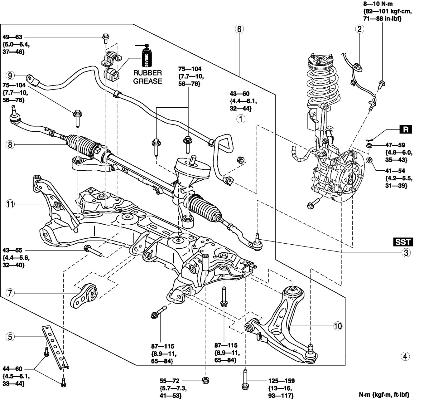
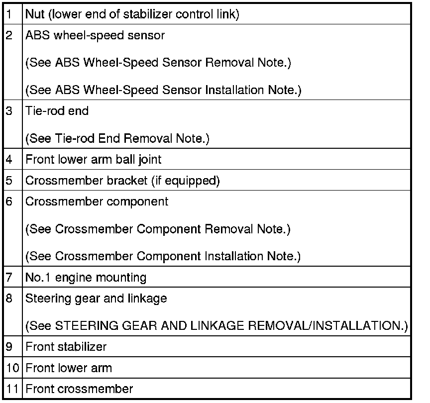
ABS Wheel-Speed Sensor Removal Note
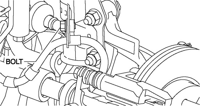
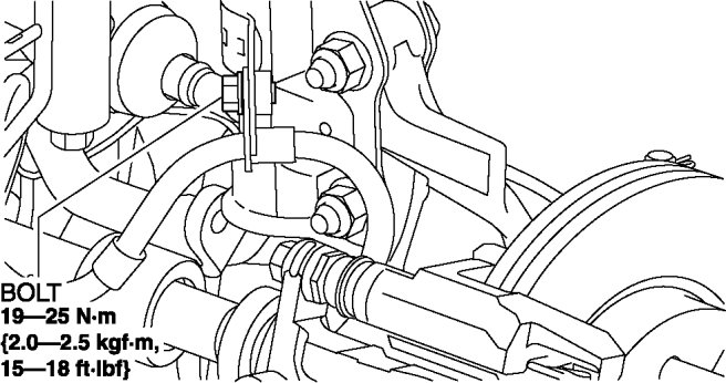
1. Remove the brake hose installation bolt shown in the figure, then remove the brake hose bracket from the shock absorber.
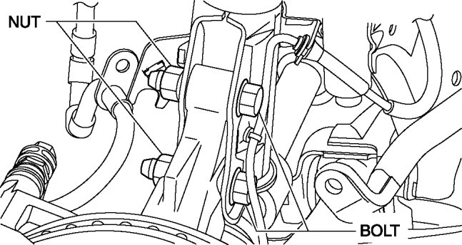
2. Remove the ABS wheel-speed sensor installation bolt, then remove the ABS wheel-speed sensor from the steering knuckle.
3. Remove the bolts and nuts shown in the figure, then disconnect the steering knuckle from the shock absorber.
4. While pressing the tabs (2 locations) of the ABS wheel-speed sensor wiring harness clip, remove the ABS wheel-speed sensor wiring harness from the shock absorber.
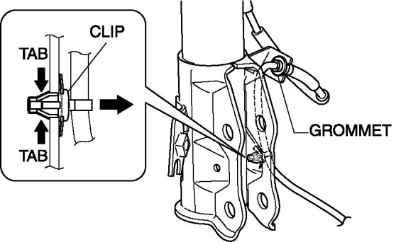
5. Remove the ABS wheel-speed sensor wiring harness grommet from the shock absorber.
6. Move the ABS wheel-speed sensor to a place out of the way.
7. Install the steering knuckle to the shock absorber, insert the bolts from the direction shown as follows, then tighten them to the specified torque.

- Vehicle left side: Insert the bolts from the vehicle rear.
- Vehicle right side: Insert the bolts from the vehicle front.
8. Install the brake hose bracket to the shock absorber, then tighten the bolt to the specified torque.
Tie-rod End Removal Note
1. Remove the locknut of the tie-rod end.
2. Detach the tie-rod end from the steering knuckle using the SST.

Crossmember Component Removal Note
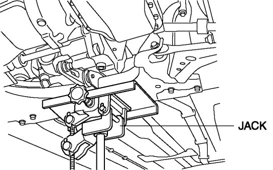
1. Support the crossmember component using a jack.
WARNING:
- Verify that the crossmember component is securely supported by a jack. If the crossmember component falls off, it could cause serious injury or death, and damage to the vehicle.
2. Detach the No.1 engine mounting from the engine. Removal and Replacement
3. Remove the front crossmember installation bolts.
4. Lower the jack slowly and remove the front crossmember component.
Crossmember Component Installation Note
1. Support the crossmember component using a jack.
WARNING:
- Verify that the crossmember component is securely supported by a jack. If the crossmember component falls off, it could cause serious injury or death, and damage to the vehicle.
2. Raise the jack slowly and install the front crossmember component.
3. Install the No.1 engine mounting (engine side). Removal and Replacement
ABS Wheel-Speed Sensor Installation Note
1. Install the ABS wheel-speed sensor wiring harness grommet to the shock absorber as shown in the figure.
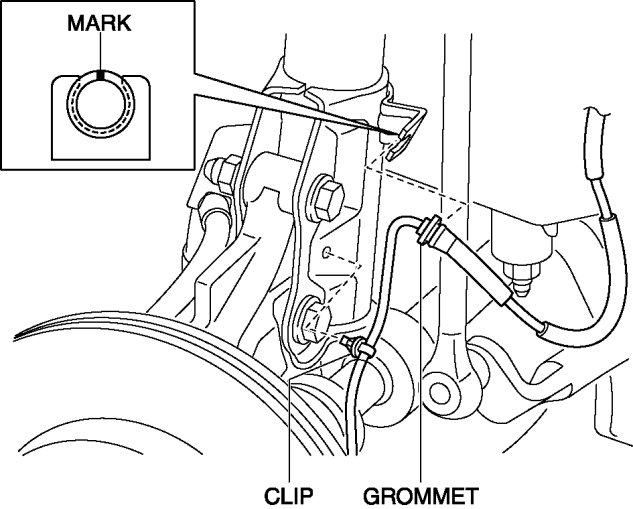
2. Install the ABS wheel-speed sensor wiring harness clip to the shock absorber.
3. Install the ABS wheel-speed sensor to the steering knuckle, then tighten the bolt (ABS wheel-speed sensor) to the specified torque.
4. Verify that the ABS wheel-speed sensor wiring harness is not twisted.
Factory Service Tools
Use the Manual With the Right Hardware
Pair factory procedures with proven DIY tools so the instructions are easier to execute.
Disclosure: Verified tool recommendations may earn an affiliate commission at no cost to you.
When to See a Mechanic
Stop DIY work and contact a certified mechanic immediately if any of the following apply:
- • You smell fuel, burning insulation, or see smoke.
- • Brakes feel soft, pull hard to one side, or make grinding noises.
- • The engine overheats, stalls repeatedly, or misfires under load.
- • You are missing required tools, torque specs, or safe lifting equipment.
- • You are not confident in the next step or safety outcome.