
Safety Warning
DIY auto repair can cause serious injury, fire, or vehicle damage. These guides are for informational purposes only. Always follow OEM torque specs, wear PPE, and consult a certified mechanic if you are unsure. You are solely responsible for your safety.
2011 Mazda RX8 2RTR-1.3LFACTORY OEM SERVICE PROCEDURE
Transmission Position Sensor/Switch: Adjustments
TRANSMISSION RANGE (TR) SWITCH ADJUSTMENT [SJ6A-EL]
CAUTION:
- Water or foreign material entering the connector can cause poor connections or corrosion. Be sure that water or foreign material do not enter the connector when disconnecting it.
1. Remove the engine cover. Service and Repair
2. Remove the battery cover.
3. Disconnect the negative battery cable.
4. Remove the front tunnel member.
5. Remove the rear tunnel member.
6. Remove the catalytic converter. Service and Repair
7. Remove the insulator.

8. Mark the manual shaft lever component as shown in the figure.
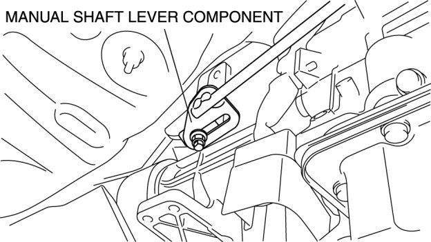
9. Separate the manual shaft lever component from selector lever.
10. Disconnect the TR switch connector.

11. Rotate the manual shaft to the N position.
CAUTION:
- Do not use an impact wrench. Hold the manual shaft lever when removing the manual shaft nut, otherwise the transmission may be damaged.
12. Set the adjustable wrench as shown in the figure to hold the manual shaft lever.
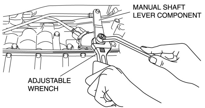
13. Remove the manual shaft nut.
14. Remove the washer and manual shaft lever component.

15. Loosen the TR switch mounting bolts.
16. Temporarily install the TR switch mounting bolt.
CAUTION:
- Improper adjustment of the TR switch will cause abnormal operation of the automatic transmission. Be sure to adjust the TR switch correctly.
17. Verify the TR switch reference line and the notch of the manual shaft are aligned.
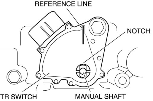
18. Tighten the TR switch mounting bolts.
Tightening torque
- 9.8-15.7 Nm {100-160 kgf-cm, 87-138 in-lbf}
19. Inspect for continuity between TR switch terminals E and H.

20. Install the manual shaft lever component and washer.
CAUTION:
- Do not use an impact wrench. Hold the manual shaft lever when tightening the manual shaft nut, otherwise the transmission may be damaged.
21. Set the adjustable wrench as shown in the figure to hold the manual shaft lever.
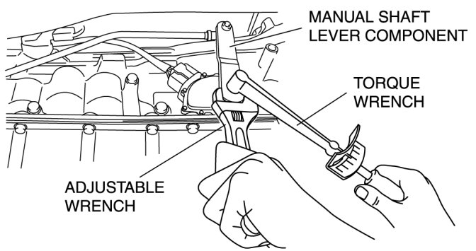
22. Tighten the manual shaft nut using a torque wrench.
Tightening torque
- 13.7-17.6 Nm {1.4-1.8 kgf-m, 11-13 ft-lbf}
23. Shift the selector lever to P position.
24. Turn the manual shaft lever to P position.
25. Inspect TR switch continuity. Testing and Inspection
26. Connect the TR switch connector.
27. Align the mark of the manual shaft lever component as shown in the figure.
28. Install the manual shaft lever component installation nut.
Tightening torque
- 10.8-14.7 Nm {1.1-1.4 kgf-m, 8.0-10.8 ft-lbf}
29. Install the insulator.
Tightening torque
- 8-11 Nm {82-112 kgf-cm, 72-97 in-lbf}
30. Install the catalytic converter. Service and Repair
31. Install the rear tunnel member.
32. Install the front tunnel member.
33. Connect the negative battery cable.
34. Install the battery cover.
35. Install the engine cover. Service and Repair
36. Inspect TR switch operation. Testing and Inspection
Factory Service Tools
Use the Manual With the Right Hardware
Pair factory procedures with proven DIY tools so the instructions are easier to execute.
Disclosure: Verified tool recommendations may earn an affiliate commission at no cost to you.
When to See a Mechanic
Stop DIY work and contact a certified mechanic immediately if any of the following apply:
- • You smell fuel, burning insulation, or see smoke.
- • Brakes feel soft, pull hard to one side, or make grinding noises.
- • The engine overheats, stalls repeatedly, or misfires under load.
- • You are missing required tools, torque specs, or safe lifting equipment.
- • You are not confident in the next step or safety outcome.