
Safety Warning
DIY auto repair can cause serious injury, fire, or vehicle damage. These guides are for informational purposes only. Always follow OEM torque specs, wear PPE, and consult a certified mechanic if you are unsure. You are solely responsible for your safety.
2010 Mazda 6 L4-2.5LFACTORY OEM SERVICE PROCEDURE
Component Tests and General Diagnostics
PCM INSPECTION [L5]
Using M-MDS
NOTE:
- PIDs for the following parts are not available on this model. Go to the appropriate part inspection.
- CMP sensor
- Main relay
1. Connect the M-MDS to the DLC-2.
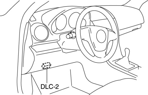
2. Switch the ignition to ON.
3. Measure the PID value.
- If PID value is not within the specification, follow the instructions in Action column.
NOTE:
- The PID/DATA MONITOR function monitors the calculated value of the input/output signals in the PCM. Therefore, an output device malfunction is not directly indicated as a malfunction of the monitored value for the output device. If a monitored value of an output device is out of specification, inspect the monitored value of the input device related to the output control.
- For input/output signals except those of the monitoring items, use a voltmeter to measure the PCM terminal voltage.
- The simulation items that are used in the ENGINE CONTROL SYSTEM OPERATION INSPECTION are as follows.
- ACCS, ALTF, ARPMDES, EVAPCP, EVAPCV, FAN_DUTY, FP, HTR11, HTR12, IMRC, IMTV, INJ_1~4, SEGRP, TEST, VT Duty1 wt
PID/DATA monitor table (reference)
PID/DATA Monitor Table (reference) Part 1:

PID/DATA Monitor Table (reference) Part 2:
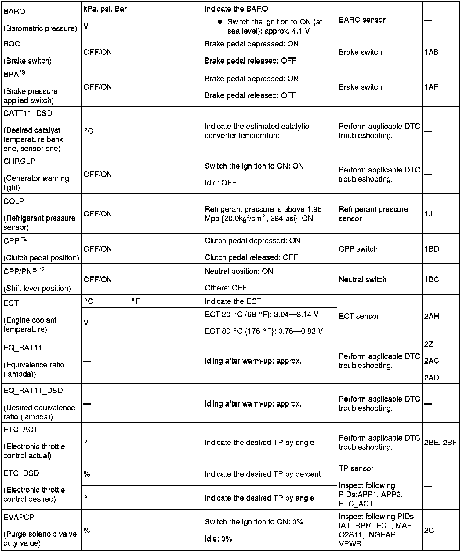
PID/DATA Monitor Table (reference) Part 3:

PID/DATA Monitor Table (reference) Part 4:

PID/DATA Monitor Table (reference) Part 5:

PID/DATA Monitor Table (reference) Part 6:
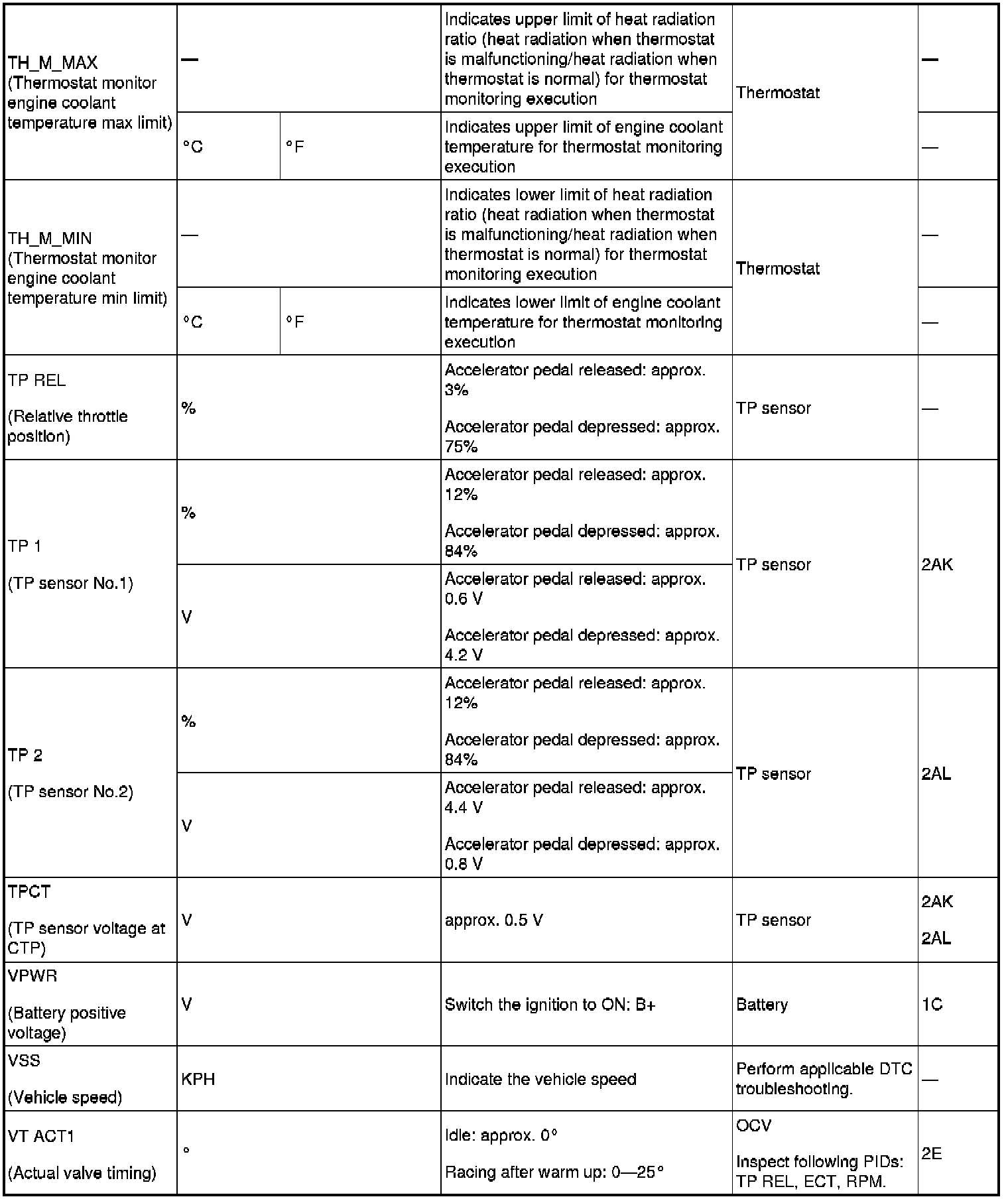
PID/DATA Monitor Table (reference) Part 7:
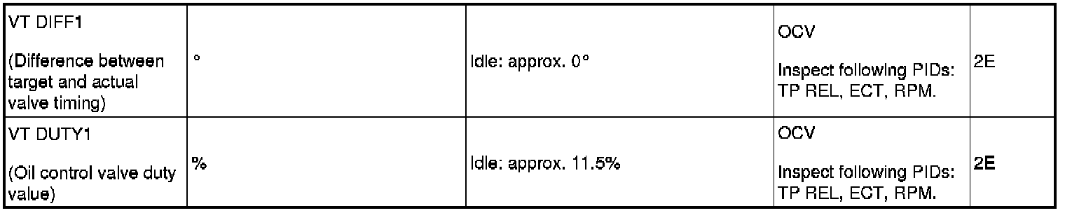
*1
Calculated value; differs from terminal voltage
*2
MTX
*3
Vehicles equipped with cruise control switch
- Following PIDs are for the ATX models. If inspects for following PIDs, On-Board Diagnostic System PID/Data Monitor Inspection - FS5A-EL
Without Using the SST
CAUTION:
- The PCM terminal voltages vary with change in measuring conditions and vehicle conditions. Always carry out a total inspection of the input systems, output systems, and PCM to determine the cause of trouble. Otherwise, a wrong diagnosis will be made.
1. Measure the voltage at each terminal.
- If any incorrect voltage is detected, inspect the related system(s), wiring harnesses and connector(s) referring to the Action column in the terminal voltage table.
Terminal voltage table (Reference)

Terminal Voltage Table (Reference) Part 1:
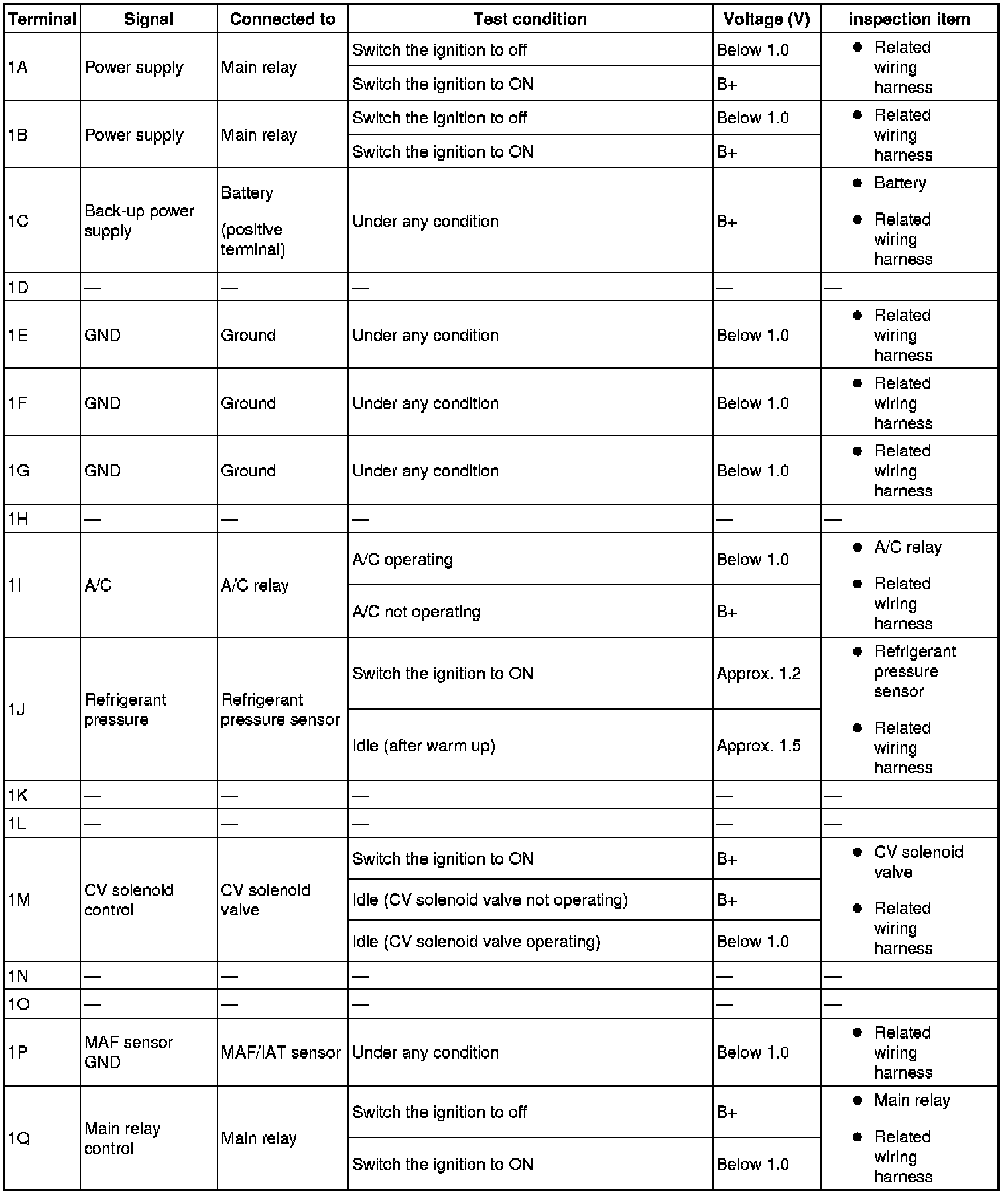
Terminal Voltage Table (Reference) Part 2:

Terminal Voltage Table (Reference) Part 3:
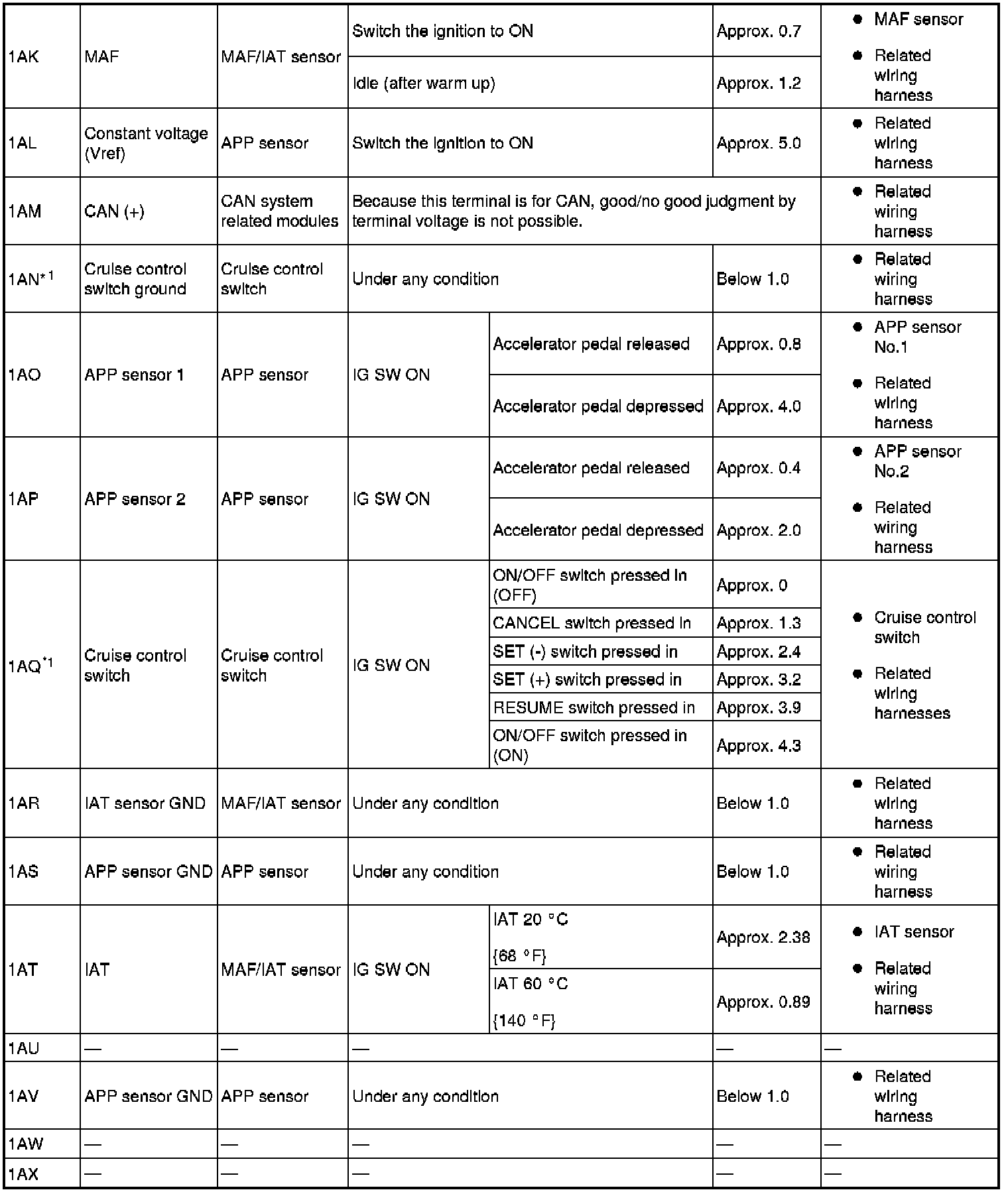
Terminal Voltage Table (Reference) Part 4:
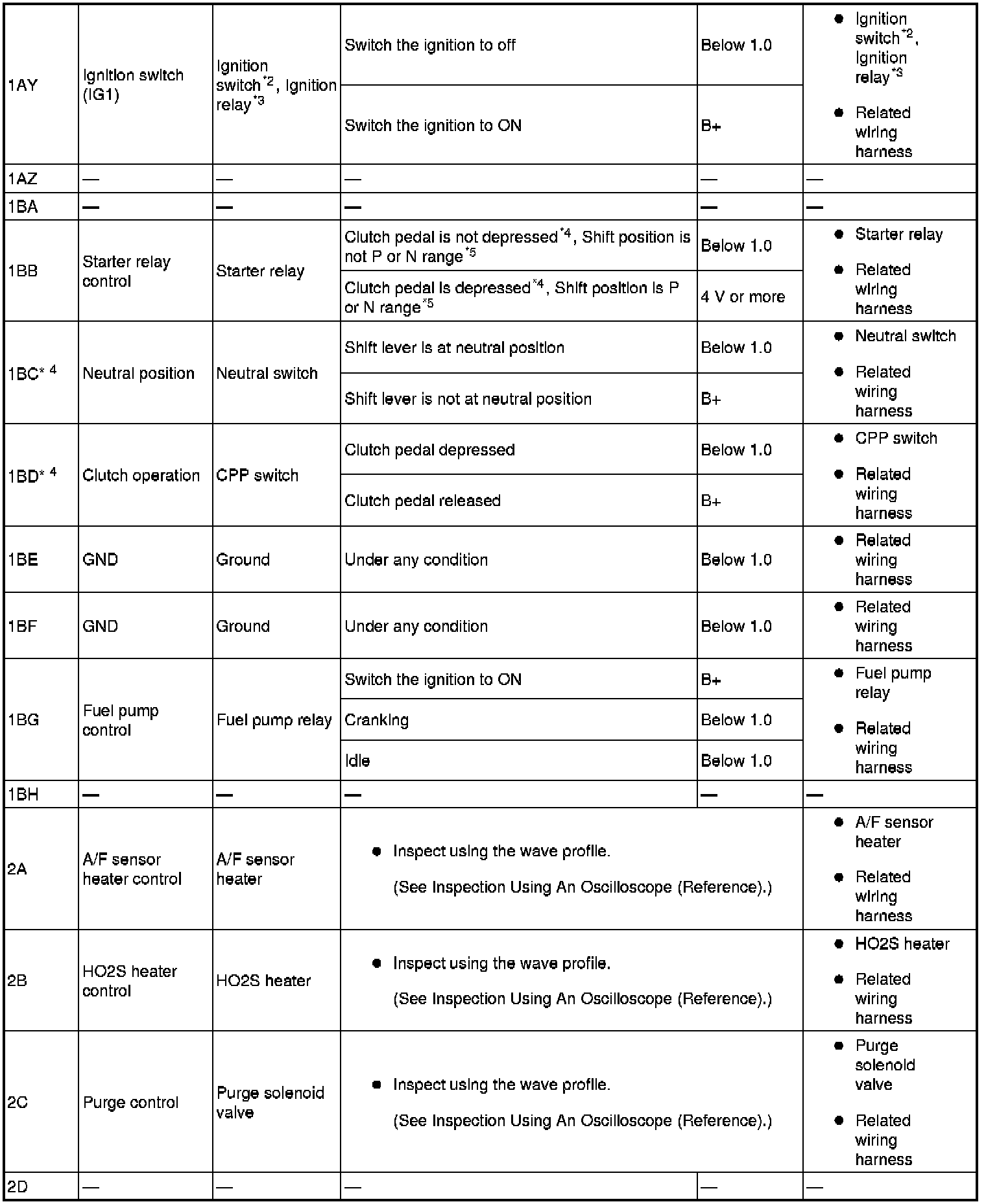
Terminal Voltage Table (Reference) Part 5:
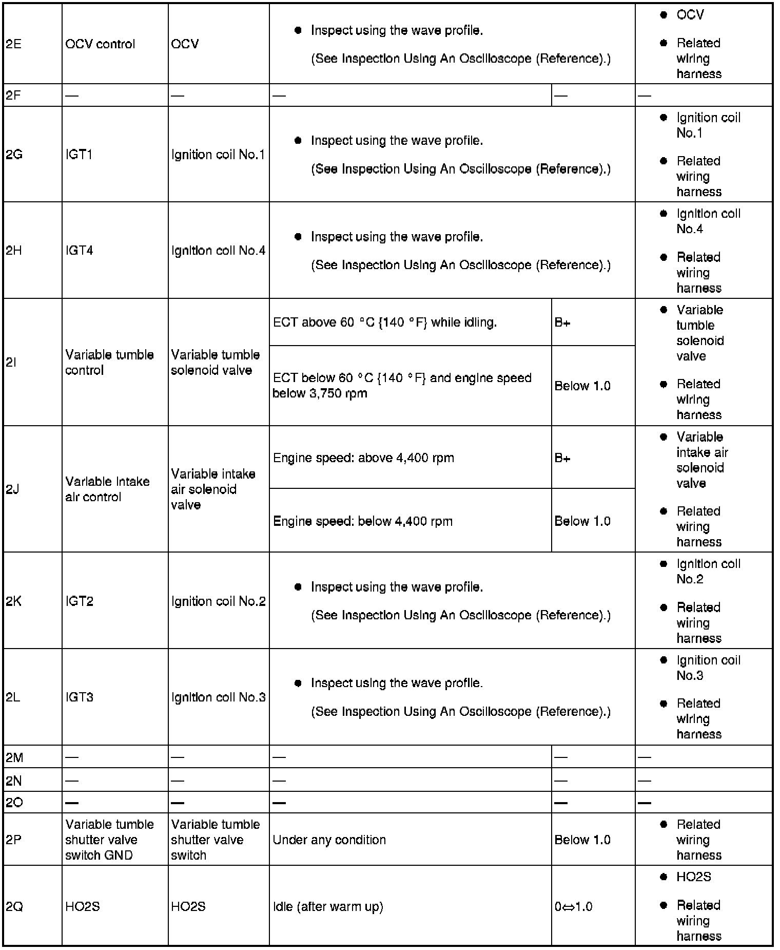
Terminal Voltage Table (Reference) Part 6:
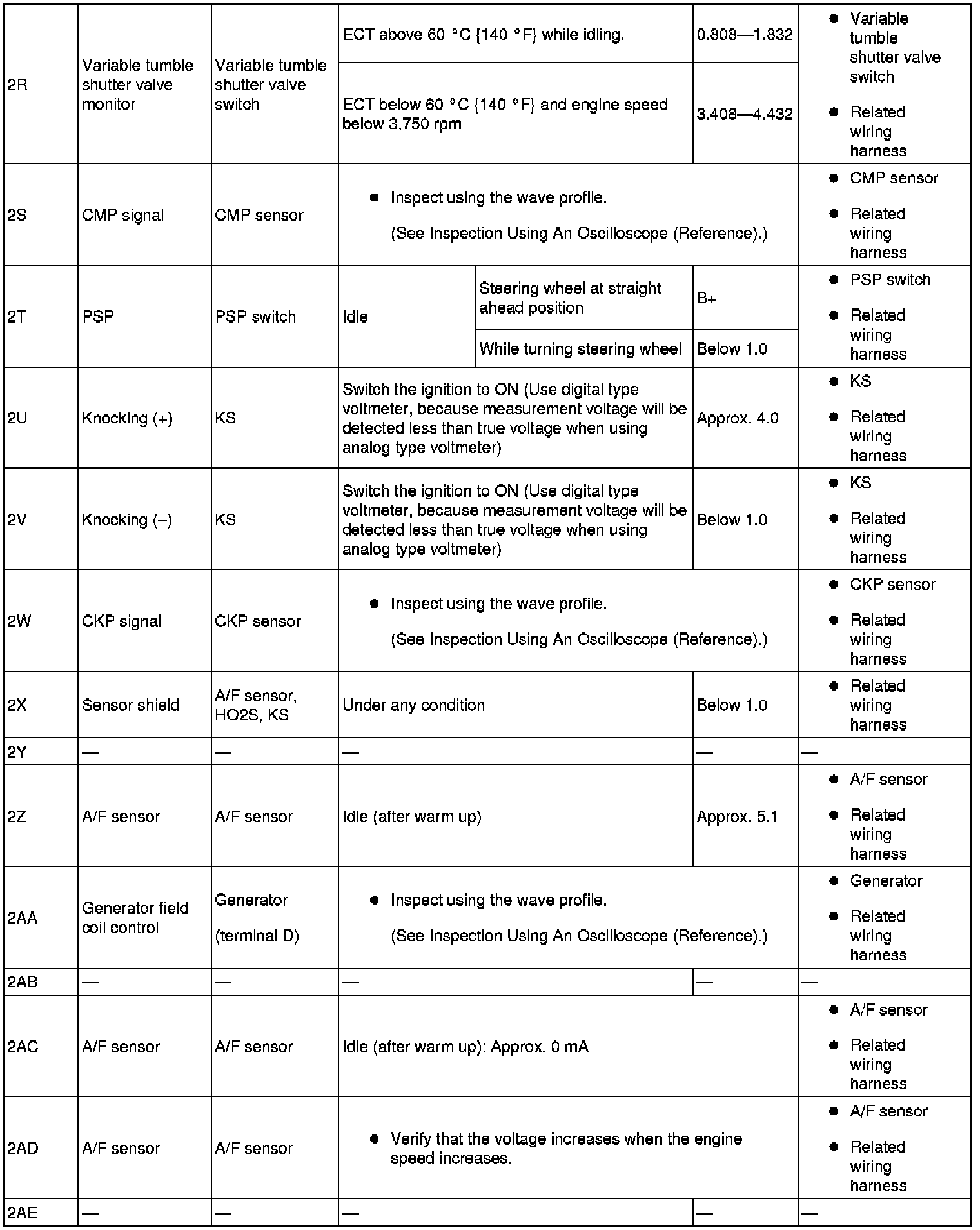
Terminal Voltage Table (Reference) Part 7:

Terminal Voltage Table (Reference) Part 8:

*1
Vehicles equipped with cruise control switch
*2
Without advanced keyless entry and push button start system
*3
With advanced keyless entry and push button start system
*4
MTX
*5
ATX
Inspection Using An Oscilloscope (Reference)
Fan control module signal

PCM terminals
- 1R-body ground(-)
Oscilloscope setting
- 5 V/DIV (Y), 20 ms/DIV (X), DC range
Vehicle condition
- Idle after warm up
A/F sensor heater control
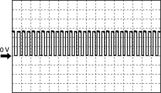
PCM terminals
- 2A(+)-body ground(-)
Oscilloscope setting
- 5 V/DIV (Y), 200 ms/DIV (X), DC range
Vehicle condition
- Idle (immediately after starting the engine)
HO2S heater control
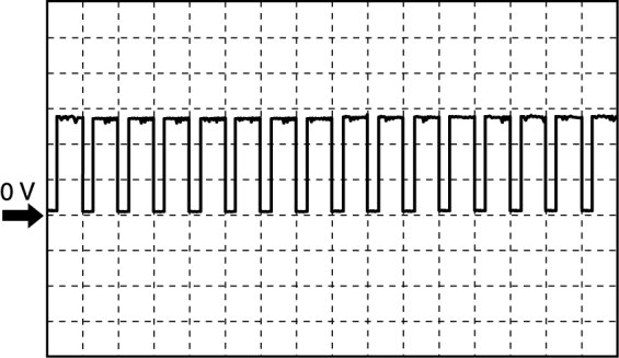
PCM terminals
- 2B(+)-body ground(-)
Oscilloscope setting
- 5 V/DIV (Y), 1 s/DIV (X), DC range
Vehicle condition
- Idle (immediately after starting the engine)
Purge control signal
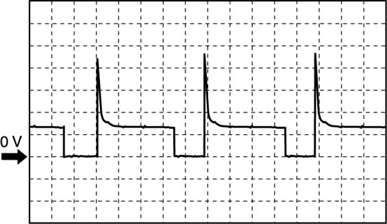
PCM terminals
- 2C(+)-body ground(-)
Oscilloscope setting
- 10 V/DIV (Y), 20 ms/DIV (X), DC range
Vehicle condition
- Idle after warm up
OCV control signal
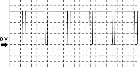
PCM terminals
- 2E(+)-body ground(-)
Oscilloscope setting
- 2 V/DIV (Y), 0.8 ms/DIV (X), DC range
Vehicle condition
- Idle after warm up
CMP sensor signal
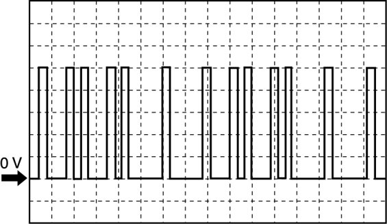
PCM terminals
- 2S(+)-body ground(-)
Oscilloscope setting
- 1 V/DIV (Y), 25 ms/DIV (X), DC range
Vehicle condition
- Idle after warm up
CKP sensor signal
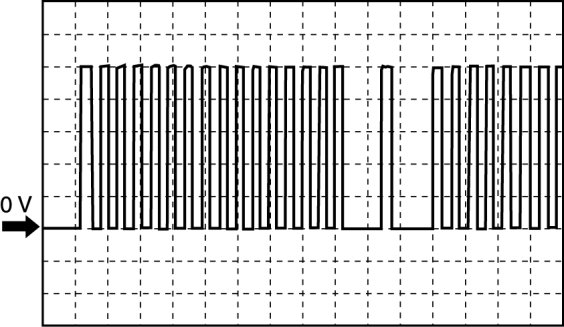
PCM terminals
- 2W(+)-body ground(-)
Oscilloscope setting
- 1 V/DIV (Y), 5 ms/DIV (X), DC range
Vehicle condition
- Idle after warm up
IGT1, IGT2, IGT3, IGT4 control signals

PCM terminals
- IGT1(ignition coil No.1): 2G(+)-body ground(-)
- IGT2(ignition coil No.2): 2K(+)-body ground(-)
- IGT3(ignition coil No.3): 2L(+)-body ground(-)
- IGT4(ignition coil No.4): 2H(+)-body ground(-)
Oscilloscope setting
- 1 V/DIV (Y), 50 ms/DIV (X), DC range
Vehicle condition
- Idle after warm up
Generator field coil control signal

PCM terminals
- 2AA(+)-body ground(-)
Oscilloscope setting
- 0.5 V/DIV (Y), 2 ms/DIV (X), DC range
Vehicle condition
- Idle after warm up
Generator output voltage signal
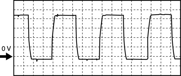
PCM terminals
- 2AF(+)-body ground(-)
Oscilloscope setting
- 2 V/DIV (Y), 2 ms/DIV (X), DC range
Vehicle condition
- Idle after warm up
Fuel injection control
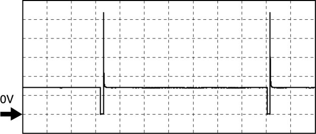
PCM terminals
- Fuel Injection No.1: 2BB(+)-body ground(-)
- Fuel Injection No.2: 2BC(+)-body ground(-)
- Fuel Injection No.3: 2BD(+)-body ground(-)
- Fuel Injection No.4: 2AZ(+)-body ground(-)
Oscilloscope setting
- 10 V/DIV (Y), 25 ms/DIV (X), DC range
Vehicle condition
- Idle after warm up
Factory Service Tools
Use the Manual With the Right Hardware
Pair factory procedures with proven DIY tools so the instructions are easier to execute.
Disclosure: Verified tool recommendations may earn an affiliate commission at no cost to you.
When to See a Mechanic
Stop DIY work and contact a certified mechanic immediately if any of the following apply:
- • You smell fuel, burning insulation, or see smoke.
- • Brakes feel soft, pull hard to one side, or make grinding noises.
- • The engine overheats, stalls repeatedly, or misfires under load.
- • You are missing required tools, torque specs, or safe lifting equipment.
- • You are not confident in the next step or safety outcome.