
Safety Warning
DIY auto repair can cause serious injury, fire, or vehicle damage. These guides are for informational purposes only. Always follow OEM torque specs, wear PPE, and consult a certified mechanic if you are unsure. You are solely responsible for your safety.
2009 Mazda RX8 2RTR-1.3LFACTORY OEM SERVICE PROCEDURE
Front Wheel Alignment
FRONT WHEEL ALIGNMENT
Specification (Unloaded Condition)
Front wheel alignment [Standard suspension]

Front wheel alignment [Sport suspension]

NOTE:
- Unloaded vehicle: Fuel tank is full. Engine coolant and engine oil are at specified level. Jack and tools are in designated position.
- Difference between the left and right dimension for camber and caster is within 1°.
Steering Angle Adjustment
1. Loosen the locknut of the tie-rod end.
2. Remove the rack boot clamp.
3. Rotate the tie rod and adjust the steering angle.
Standard steering angle
- Inner: 38°36'±3°
- Outer: 33°18'±3°
NOTE:
- Rotate and adjust the tie rod. The difference between right and left dimension L shown in the figure should be within the specification.

- Standard
3 mm {0.12 in} or less
4. Tighten the locknut of the tie-rod end.
Tightening torque
- 68.6-98.0 Nm {7.00-9.99 kgf-m, 50.6-72.2 ft-lbf}
5. Correct the rack boot deformation.
6. Install and fix the rack boot clamp.
7. After adjusting the steering angle, always inspect and adjust the toe angle.
Camber Adjustment
CAUTION:
- Adjust the camber before adjusting the caster.
NOTE:
- The camber and caster change largely if the front cam is adjusted due to the suspension construction. If the rear cam is adjusted, the caster largely, however, the camber barely changes. Therefore, adjust the camber (front cam) and then the caster (rear cam) to adjust the alignment efficiently.
1. Loosen the fixing nut of the adjusting cam bolt (front lower arm front side).

2. Rotate the adjusting cam bolt in either direction to adjust the camber.

Standard suspension
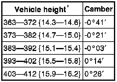
Sport suspension

*
From the end of the front fender to the center of the wheel (mm {in})

NOTE:
- Refer to the figure for the adjusting angle per one graduation.

3. Tighten the nut.
Tightening torque
- 117.7-137.3 Nm {12.1-14.0 kgf-m, 86.9-101.2 ft-lbf}
4. Adjust the toe-in.
Caster Adjustment
CAUTION:
- Adjust the caster after adjusting the camber.
NOTE:
- The camber and caster change largely if the front cam is adjusted due to the suspension construction. If the rear cam is adjusted, the caster largely, however, the camber barely changes. Therefore, adjust the camber (front cam) and then the caster (rear cam) to adjust the alignment efficiently.
1. Loosen the installation nut of the adjusting cam bolt (front lower arm rear side).

2. Rotate the adjusting cam bolt in either direction to adjust the caster.
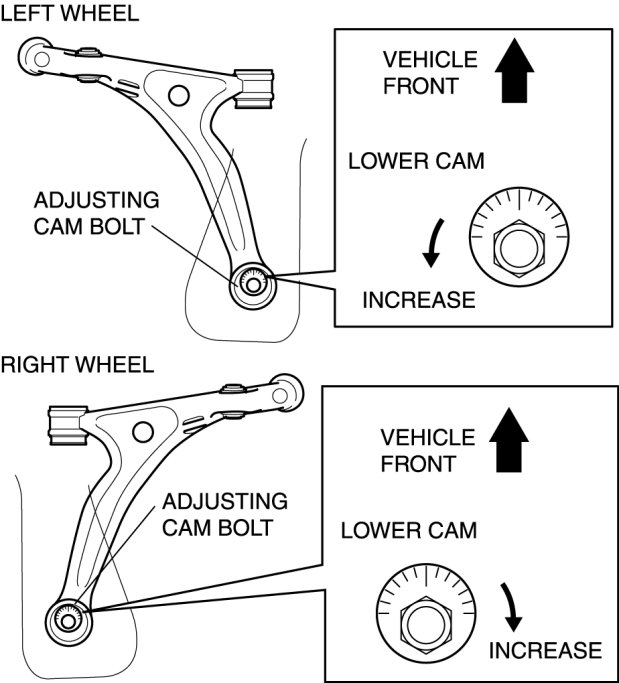
Standard suspension

Sport suspension

*
From the end of the rear fender to the center of the wheel (mm {in})

NOTE:
- Refer to the following figure for the adjusting amount per one graduation.

3. Tighten the nut.
Tightening torque
- 117.7-137.3 Nm {12.1-14.0 kgf-m, 86.9-101.2 ft-lbf}
4. Adjust the camber and total toe-in.
Total Toe-in Adjustment
1. Loosen the locknut of the tie-rod end.
2. Remove the rack boot clamp.
3. Adjust the total toe-in by rotating each tie rod (left and right) in the opposite directions by the same amount respectively.
Total Toe-in Standard
- 2±4 mm {0.08±0.15 in} (0°11'±21')
NOTE:
- Toe angle changes by approx. 5 mm {0.2 in} per one rotation of the tie rod for one wheel.
- Each tie rod has a left-hand thread. When increasing the toe-in angle, rotate the right tie rod toward the rear of the vehicle, and rotate the left tie rod toward the front of the vehicle by the same amount.
4. Tighten the locknut of the tie-rod end.
Tightening torque
- 68.6-98.0 Nm {7.00-9.99 kgf-m, 50.6-72.2 ft-lbf}
5. Verify that the rack boot does not have any twisting, and install the rack boot clamp.
Factory Service Tools
Use the Manual With the Right Hardware
Pair factory procedures with proven DIY tools so the instructions are easier to execute.
Disclosure: Verified tool recommendations may earn an affiliate commission at no cost to you.
When to See a Mechanic
Stop DIY work and contact a certified mechanic immediately if any of the following apply:
- • You smell fuel, burning insulation, or see smoke.
- • Brakes feel soft, pull hard to one side, or make grinding noises.
- • The engine overheats, stalls repeatedly, or misfires under load.
- • You are missing required tools, torque specs, or safe lifting equipment.
- • You are not confident in the next step or safety outcome.