
Safety Warning
DIY auto repair can cause serious injury, fire, or vehicle damage. These guides are for informational purposes only. Always follow OEM torque specs, wear PPE, and consult a certified mechanic if you are unsure. You are solely responsible for your safety.
2008 Mazda 5 L4-2.3LFACTORY OEM SERVICE PROCEDURE
Oscilloscope Patterns and Waveforms
Inspection Using An Oscilloscope (Reference)

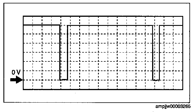
Cooling fan control signal

PCM terminals
- 1 R (+)-body ground (-)
Oscilloscope setting
- 5 V/DIV (Y), 1 ms/DIV (X), DC range
Vehicle condition
- Idle after warm up
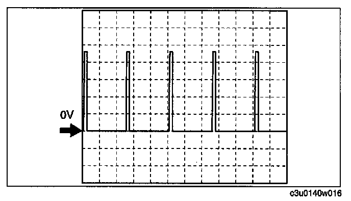
Purge control signal
PCM terminals
- 2C (+)-body ground (-)
Oscilloscope setting
- 2 V/DIV (Y), 10 ms/DIV (X), DC range
Vehicle condition
- Idle after warm up
APP sensor signal
Accelerator pedal is released
Accelerator pedal is depressed
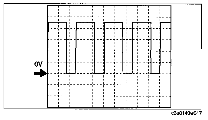
PCM terminals
- 1AO (+)-body ground (-)
Oscilloscope setting
- 2.5 V/DIV (Y), 2 ms/DIV (X), DC range
Vehicle condition
- Ignition switch is turned to the ON position.
(engine off)
OCV signal
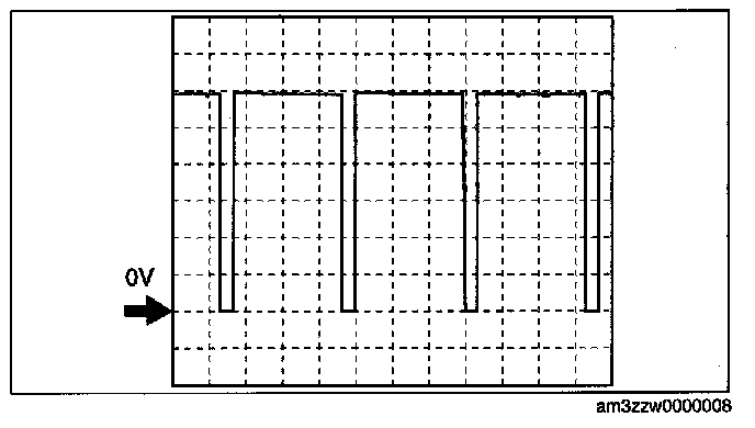
PCM terminals
- 2E (+)-body ground (-)
Oscilloscope setting
- 2 V/DIV (Y), 0.8 ms/DIV (X), DC range
Vehicle condition
- Idle after warm up
CMP signal
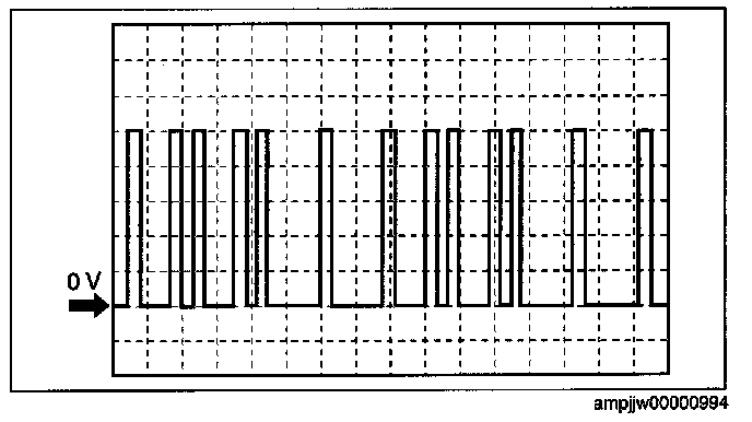
PCM terminals
- 2S (+)-body ground (-)
Oscilloscope setting
- 1 V/DIV (Y), 25 ms/DIV (X), DC range
Vehicle condition
- Idle after warm up
CKP signal

PCM terminals
- 2W (+)-body ground (-)
Oscilloscope setting
- 1 V/DIV (Y), 2.5 ms/DIV (X), DC range
Vehicle condition
- Idle after warm up
Generator field coil control signal

PCM terminals
- 2M (+)-body ground (-)
Oscilloscope setting
- 0.5 V/DIV (Y), 2 ms/DIV (X), DC range
Vehicle condition
- Idle after warm up (engine speed approx. 650 rpm, no load, A/C off)
Generator output voltage signal

PCM terminals
- 2AF (+)-body ground (-)
Oscilloscope setting
- 2 V/DIV (Y), 1 ms/DIV (X), DC range
Vehicle condition
- Idle after warm up
IGT1, IGT2, IGT3, IGT4 signals

PCM terminals
- IGT1 (No.1): 2G (+)-body ground (-)
- 10T2 (No.2): 2K (+)-body ground (-)
- IGT3 (No.3): 2L (+)-body ground (-)
- IGT4 (No.4): 2H (+)-body ground (-)
Oscilloscope setting
- 4 V/DIV (Y), 0.01 ms/DIV (X), DC range
Vehicle condition
- Idle after warm up
Fuel injection signal

PCM terminals
- Fuel Injection No.1: 2BB (+)-body ground (-)
- Fuel Injection No.2: 2BC (+)-body ground (-)
- Fuel Injection No.3: 2BD (+)-body ground (-)
Oscilloscope setting
- 4V/DIV (Y), 20 ms/DIV (X), DC range
Vehicle condition
- Idle after warm up
Front HO2S heater control signal
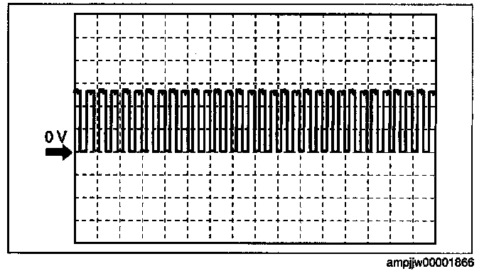
PCM terminals
- 2A (+)-body ground (-)
Oscilloscope setting
- 5 V/DIV (Y), 200 ms/DIV (X), DC range
Vehicle condition
- Idle after warm up (engine speed approx. 650 rpm, no load, A/C off)
Rear HO2S heater control signal
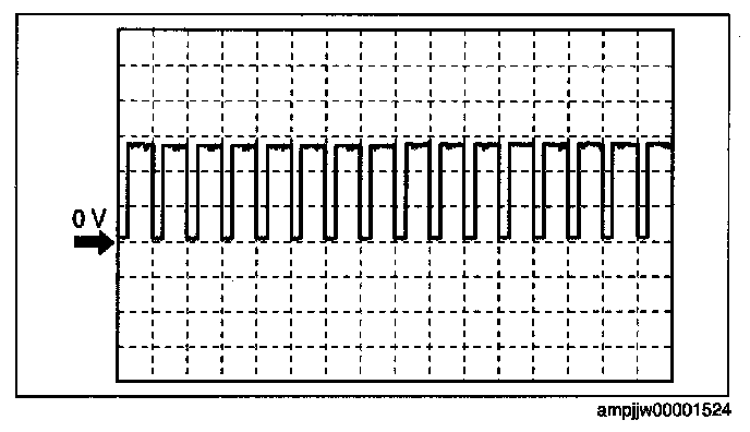
PCM terminals
- 2B (+)-body ground (-)
Oscilloscope setting
- 5 V/DIV (Y), 1 s/DIV (X), DC range
Vehicle condition
- Idle after warm up (engine speed approx. 650 rpm, no load, A/C off)
Factory Service Tools
Use the Manual With the Right Hardware
Pair factory procedures with proven DIY tools so the instructions are easier to execute.
Disclosure: Verified tool recommendations may earn an affiliate commission at no cost to you.
When to See a Mechanic
Stop DIY work and contact a certified mechanic immediately if any of the following apply:
- • You smell fuel, burning insulation, or see smoke.
- • Brakes feel soft, pull hard to one side, or make grinding noises.
- • The engine overheats, stalls repeatedly, or misfires under load.
- • You are missing required tools, torque specs, or safe lifting equipment.
- • You are not confident in the next step or safety outcome.