
Safety Warning
DIY auto repair can cause serious injury, fire, or vehicle damage. These guides are for informational purposes only. Always follow OEM torque specs, wear PPE, and consult a certified mechanic if you are unsure. You are solely responsible for your safety.
2007 Mazda RX8 2RTR-1.3LFACTORY OEM SERVICE PROCEDURE
Oscilloscope Patterns and Waveforms
Inspection Using An Oscilloscope (Reference)
NOTE: The duty ratio for the wave pattern can vary with the control conditions. Therefore determine comprehensively where the malfunction occurs among the input systems, output systems, and the PCM.
Throttle control (+)

- Terminal connected: 1B (+)-Negative battery terminal
- Oscilloscope setting: 5 V/DIV (Y): 0.4 ms/DIV (X), DC range
- Measurement condition: IG SW ON
Throttle control (-)

- Terminal connected1C (+)-Negative battery terminal
- Oscilloscope setting: 5 V/DIV (Y): 1 ms/DIV (X), DC range
- Measurement condition: As soon as the accelerator pedal is fully released from the fully depressed position while the ignition switch is at ON (engine off).
Front HO2S heater control

- Terminal connected:1 V (+)-Negative battery terminal
- Oscilloscope setting: 5 V/DIV (Y): 50 ms/DIV (X), DC range
- Measurement condition: Idling after warm-up (no load)
Rear HO2S heater control

- Terminal connected: 2 A (+)-Negative battery terminal
- Oscilloscope setting: 5 V/DIV (Y): 5- ms/DIV (X), DC range
- Measurement condition: Idling after warm-up (no load)
Fuel injector (FS, RS) control

- Terminal connected:
FS: 2G (+)-Negative battery terminal
RS: 2D (+)-Negative battery terminal
- Oscilloscope setting: 5 V/DIV (Y): 5 ms/DIV (X), DC range
- Measurement condition: Racing after warm-up (no load)
Field coil control (Generator)

- Terminal connected: 21 (+)-Negative battery terminal
- Oscilloscope setting: 0.5 V/DIV (Y): 1 ms/DIV (X), DC range
- Measurement condition: Idling after warm-up (no load)
Fuel injector (FP1, RP1) control
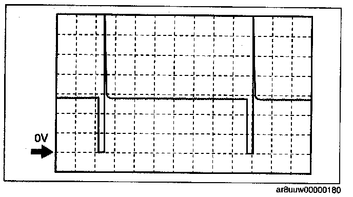
- Terminal connected:
FP1: 2M (+)-Negative battery terminal
RP1: 2J (+)-Negative battery terminal
- Oscilloscope setting: 5 V/DIV (Y):10 ms/DIV (X), DC range
- Measurement condition: Idling after warm-up (no load)

- Terminal connected:
FP1: 2M (+)-Negative battery terminal
RP1 : 2J (+)-Negative battery terminal
- Oscilloscope setting: 5 V/DIV V): 10 ms/DIV (X), DC range
- Measurement condition: Cranking while the engine is cold. (ECT: Approx. 20 °C {68 °F})
Purge control

- Terminal connected:2P (+)-Negative battery terminal
- Oscilloscope setting: 5 V/DIV (Y): 20 ms/DIV (X), DC range
- Measurement condition: Idling after warm-up (no load)
NOTE: Purge control might not be activated depending on the engine conditions.
Generator output voltage

- Terminal connected: 2T (+)-Negative battery terminal
- Oscilloscope setting: 2 V/DIV (Y): 2 ms/DIV (X), DC range
- Measurement condition: Idling after warm-up (no load)
Eccentric shaft position sensor
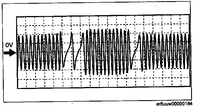
- Terminal connected: 2U (+)-Negative battery terminal
- Oscilloscope setting: 2 V/DIV (Y): 5 ms/DIV (X), DC range
- Measurement condition: Idling after warm-up (no load)
Metering oil pump control 1

- Terminal connected: 2W (+)-Negative battery terminal
- Oscilloscope setting: 5 V/DIV (Y): 2 ms/DIV (X), DC range
- Measurement condition: Just after the ignition switch is off after warm-up (no load)
Metering oil pump control 2

- Terminal connected: 2AB (+)-Negative battery terminal
- Oscilloscope setting: 5 V/DIV (Y): 2 ms/DIV (X), DC range
- Measurement condition: Just after the ignition switch is off after warm-up (no load)
Metering oil pump control 3

- Terminal connected: 2V (+)-Negative battery terminal
- Oscilloscope setting: 5 V/DIV (Y):2 ms/DIV (X), DC range
- Measurement condition: Just after the ignition switch is off after warm-up (no load)
Metering oil pump control 4

- Terminal connected: 2Y (+)-Negative battery terminal
- Oscilloscope setting: 5 V/DIV (Y): 2 ms/DIV (X), DC range
- Measurement condition: Just after the ignition switch is off after warm-up (no load)
Ignition coil (UF, UR, T/F, T/R)

- Terminal connected:
L/F: 2AA (+)-Negative battery terminal
L/R:2Z (+)-Negative battery terminal
T/F: 2AD (+)-Negative battery terminal
T/R: 2AC (+)-Negative battery terminal
- Oscilloscope setting: 2 V/DIV (Y):10 ms/DIV (X), DC range
- Measurement condition: Idling after warm-up (no load)
Fuel injector (FP2, RF2) control

- Terminal connected:
FP2: 3A (+)-Negative battery terminal
RP2: 3D (+)-Negative battery terminal
- Oscilloscope setting: 5 V/DIV (Y): 5 ms/DIV (X), DC range
- Measurement condition: Racing after warm-up (no load)
APV motor control (+)

- Terminal connected: 3G (+)-Negative battery terminal
- Oscilloscope setting: 5 V/DIV (Y): 20 ms/DIV (X), DC range
- Measurement condition: Engine speed 6,250 rpm or more after warm-up (approx. 2 s after the APV remains open)
APV motor control (-)

- Terminal connected: 3J (+)-Negative battery terminal
- Oscilloscope setting: 5 V/DIV (Y): 20 ms/DIV (X), DC range
- Measurement condition: Within 20 s from 2 s after the accelerator is released from the engine speed at 6,250 rpm or more after warm-up.
NOTE: The duty ratio for the wave pattern can vary with the control conditions. Therefore determine comprehensively where the malfunction occurs among the input systems, output systems, and the PCM.
Throttle control (+)
- Terminal connected: 1B (+)-Negative battery terminal
- Oscilloscope setting: 5 V/DIV (Y): 0.4 ms/DIV (X), DC range
- Measurement condition: IG SW ON
Throttle control (-)
- Terminal connected1C (+)-Negative battery terminal
- Oscilloscope setting: 5 V/DIV (Y): 1 ms/DIV (X), DC range
- Measurement condition: As soon as the accelerator pedal is fully released from the fully depressed position while the ignition switch is at ON (engine off).
Front HO2S heater control
- Terminal connected:1 V (+)-Negative battery terminal
- Oscilloscope setting: 5 V/DIV (Y): 50 ms/DIV (X), DC range
- Measurement condition: Idling after warm-up (no load)
Rear HO2S heater control
- Terminal connected: 2 A (+)-Negative battery terminal
- Oscilloscope setting: 5 V/DIV (Y): 5- ms/DIV (X), DC range
- Measurement condition: Idling after warm-up (no load)
Fuel injector (FS, RS) control
- Terminal connected:
FS: 2G (+)-Negative battery terminal
RS: 2D (+)-Negative battery terminal
- Oscilloscope setting: 5 V/DIV (Y): 5 ms/DIV (X), DC range
- Measurement condition: Racing after warm-up (no load)
Field coil control (Generator)
- Terminal connected: 21 (+)-Negative battery terminal
- Oscilloscope setting: 0.5 V/DIV (Y): 1 ms/DIV (X), DC range
- Measurement condition: Idling after warm-up (no load)
Fuel injector (FP1, RP1) control
- Terminal connected:
FP1: 2M (+)-Negative battery terminal
RP1: 2J (+)-Negative battery terminal
- Oscilloscope setting: 5 V/DIV (Y):10 ms/DIV (X), DC range
- Measurement condition: Idling after warm-up (no load)
- Terminal connected:
FP1: 2M (+)-Negative battery terminal
RP1 : 2J (+)-Negative battery terminal
- Oscilloscope setting: 5 V/DIV V): 10 ms/DIV (X), DC range
- Measurement condition: Cranking while the engine is cold. (ECT: Approx. 20 °C {68 °F})
Purge control
- Terminal connected:2P (+)-Negative battery terminal
- Oscilloscope setting: 5 V/DIV (Y): 20 ms/DIV (X), DC range
- Measurement condition: Idling after warm-up (no load)
NOTE: Purge control might not be activated depending on the engine conditions.
Generator output voltage
- Terminal connected: 2T (+)-Negative battery terminal
- Oscilloscope setting: 2 V/DIV (Y): 2 ms/DIV (X), DC range
- Measurement condition: Idling after warm-up (no load)
Eccentric shaft position sensor
- Terminal connected: 2U (+)-Negative battery terminal
- Oscilloscope setting: 2 V/DIV (Y): 5 ms/DIV (X), DC range
- Measurement condition: Idling after warm-up (no load)
Metering oil pump control 1
- Terminal connected: 2W (+)-Negative battery terminal
- Oscilloscope setting: 5 V/DIV (Y): 2 ms/DIV (X), DC range
- Measurement condition: Just after the ignition switch is off after warm-up (no load)
Metering oil pump control 2
- Terminal connected: 2AB (+)-Negative battery terminal
- Oscilloscope setting: 5 V/DIV (Y): 2 ms/DIV (X), DC range
- Measurement condition: Just after the ignition switch is off after warm-up (no load)
Metering oil pump control 3
- Terminal connected: 2V (+)-Negative battery terminal
- Oscilloscope setting: 5 V/DIV (Y):2 ms/DIV (X), DC range
- Measurement condition: Just after the ignition switch is off after warm-up (no load)
Metering oil pump control 4
- Terminal connected: 2Y (+)-Negative battery terminal
- Oscilloscope setting: 5 V/DIV (Y): 2 ms/DIV (X), DC range
- Measurement condition: Just after the ignition switch is off after warm-up (no load)
Ignition coil (UF, UR, T/F, T/R)
- Terminal connected:
L/F: 2AA (+)-Negative battery terminal
L/R:2Z (+)-Negative battery terminal
T/F: 2AD (+)-Negative battery terminal
T/R: 2AC (+)-Negative battery terminal
- Oscilloscope setting: 2 V/DIV (Y):10 ms/DIV (X), DC range
- Measurement condition: Idling after warm-up (no load)
Fuel injector (FP2, RF2) control
- Terminal connected:
FP2: 3A (+)-Negative battery terminal
RP2: 3D (+)-Negative battery terminal
- Oscilloscope setting: 5 V/DIV (Y): 5 ms/DIV (X), DC range
- Measurement condition: Racing after warm-up (no load)
APV motor control (+)
- Terminal connected: 3G (+)-Negative battery terminal
- Oscilloscope setting: 5 V/DIV (Y): 20 ms/DIV (X), DC range
- Measurement condition: Engine speed 6,250 rpm or more after warm-up (approx. 2 s after the APV remains open)
APV motor control (-)
- Terminal connected: 3J (+)-Negative battery terminal
- Oscilloscope setting: 5 V/DIV (Y): 20 ms/DIV (X), DC range
- Measurement condition: Within 20 s from 2 s after the accelerator is released from the engine speed at 6,250 rpm or more after warm-up.
Factory Service Tools
Use the Manual With the Right Hardware
Pair factory procedures with proven DIY tools so the instructions are easier to execute.
Disclosure: Verified tool recommendations may earn an affiliate commission at no cost to you.
When to See a Mechanic
Stop DIY work and contact a certified mechanic immediately if any of the following apply:
- • You smell fuel, burning insulation, or see smoke.
- • Brakes feel soft, pull hard to one side, or make grinding noises.
- • The engine overheats, stalls repeatedly, or misfires under load.
- • You are missing required tools, torque specs, or safe lifting equipment.
- • You are not confident in the next step or safety outcome.