
Safety Warning
DIY auto repair can cause serious injury, fire, or vehicle damage. These guides are for informational purposes only. Always follow OEM torque specs, wear PPE, and consult a certified mechanic if you are unsure. You are solely responsible for your safety.
2007 Mazda CX-9 V6-3.5LFACTORY OEM SERVICE PROCEDURE
Electrical System
ELECTRICAL SYSTEM
Electrical Parts
Battery cable
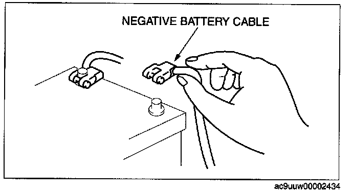
- Before disconnecting connectors or removing electrical parts, disconnect the negative battery cable.
Wiring Harness

- To remove the wiring harness from the clip in the engine room, pry up the hook of the clip using a flathead screwdriver.

CAUTION: Do not remove the wiring harness protective tape. Otherwise, the wires could rub against the body, which could result in water penetration and electrical shorting.
Connectors
Disconnecting connectors
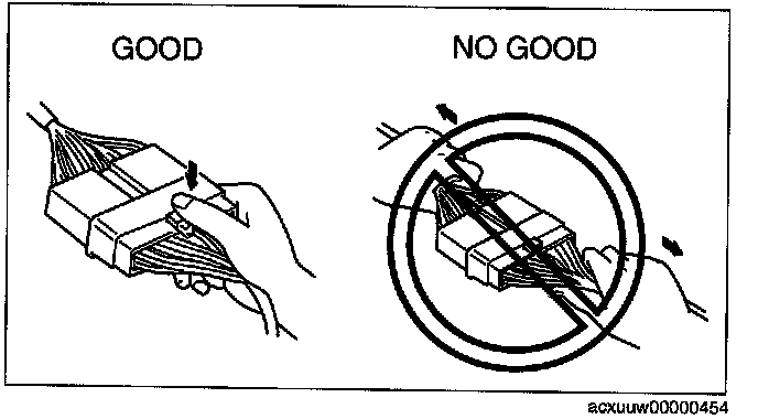
- When disconnecting a connector, grasp the connectors, not the wires.

- Connectors can be disconnected by pressing or pulling the lock lever as shown.
Locking connector

- When locking connectors, listen for a click indicating they are securely locked.
Inspection
CAUTION: To prevent damage to the terminal, wrap a thin wire around the tester probe before inserting into terminal.

- When a tester is used to inspect for continuity or measuring voltage, insert the tester probe from the wiring harness side.
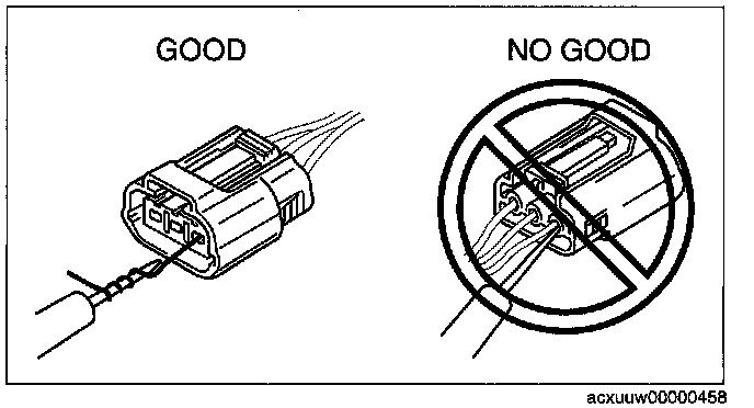
- Inspect the terminals of waterproof connectors from the connector side since they cannot be accessed from the wiring harness side.
Terminals
Inspection

- Pull lightly on individual wires to verify that they are secured in the terminal.
Replacement

- Use the appropriate tools to remove a terminal as shown. When installing a terminal, be sure to insert it until it locks securely.
- Insert a thin piece of metal from the terminal side of the connector and with the terminal locking tab pressed down, pull the terminal out from the connector.
Sensors, Switches, and Relays
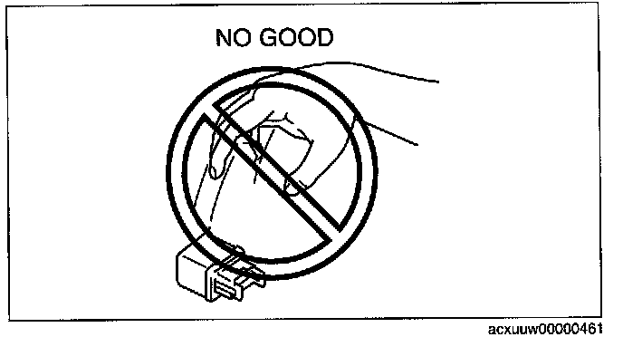
- Handle sensors, switches, and relays carefully. Do not drop them or strike them against other objects.
Wiring Harness
Wiring color codes
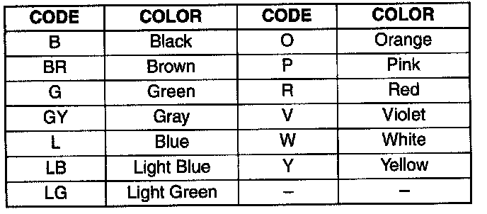

- Two-color wires are indicated by a two-color code symbol.
- The first letter indicates the base color of the wire and the second is the color of the stripe.
Fuse
Replacement

- When replacing a fuse, be sure to replace it with one of the same capacity. If a fuse malfunctions again, the circuit probably has a short and the wiring should be inspected.
- Be sure the negative battery terminal is disconnected before replacing a main fuse.

- When replacing a pullout fuse, use the fuse puller.
Viewing orientation for Connectors
- The viewing orientation for connectors is indicated with a symbol.
- The figures showing the viewing orientation are the same as those used in Wiring Diagrams. The viewing orientations are shown in the following three ways.
Part-side connector

The viewing orientation for part-side connectors is from the terminal side.
* : Part names are shown only when there are multiple connector drawings.

Vehicle harness-side connector
The viewing orientation for vehicle wiring harness- side connectors is from the wiring harness side.
* : Part names are shown only when there are multiple connector drawings.
Other
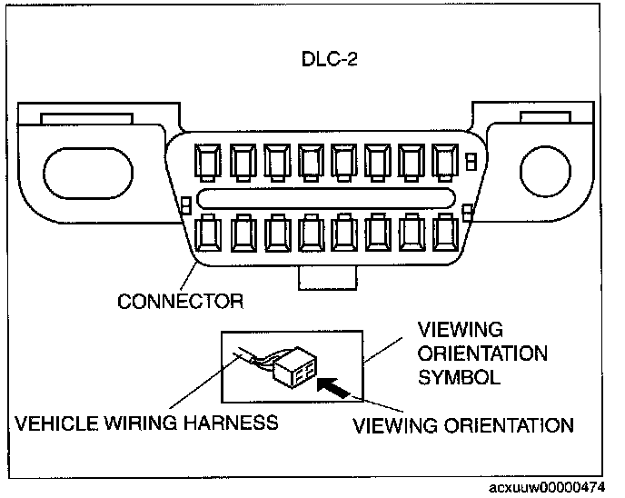
When it is necessary to show the terminal side of the vehicle wiring harness-side connectors, such as the following connectors, the viewing orientation is from the terminal side.
- Main fuse block and the main fuse block relays
- Data link connector
- Check connector
- Relay box
Electrical Troubleshooting Tools
Jumper wire
CAUTION: Do not connect a jumper wire from the power source line to a body ground. This may cause burning or other damage to wiring harnesses or electronic components.

- A jumper wire is used to create a temporary circuit. Connect the jumper wire between the terminals of a circuit to bypass a switch.
Voltmeter
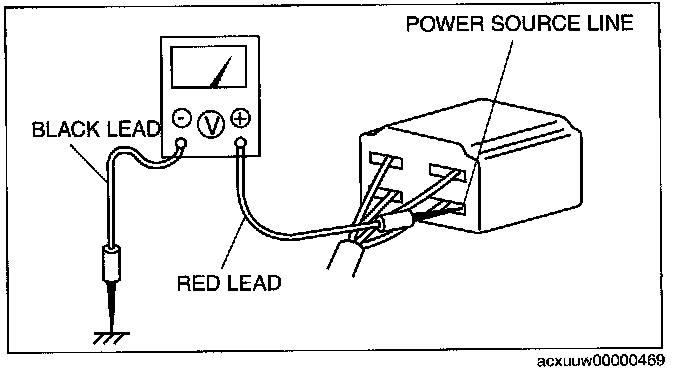
- The DC voltmeter is used to measure circuit voltage. A voltmeter with a range of 15 V or more is used by connecting the positive (+) probe (red lead wire) to the point where voltage will be measured and the negative (-) probe (black lead wire) to a body ground.
Ohmmeter
CAUTION: Do not connect the ohmmeter to any circuit where voltage is applied. This will damage the ohmmeter.

- The ohmmeter is used to measure the resistance between two points in a circuit and to inspect for continuity and short circuits.
Precautions Before Welding
A vehicle has various electrical parts. To protect the parts from excessive current generated when welding, be sure to perform the following procedure.
1. Turn the ignition switch to the LOCK position.

2. Disconnect the battery cables.

3. Securely connect the welding machine ground near the welding area.
4. Cover the peripheral parts of the welding area to protect them from weld spatter.
Electrical Parts
Battery cable
- Before disconnecting connectors or removing electrical parts, disconnect the negative battery cable.
Wiring Harness
- To remove the wiring harness from the clip in the engine room, pry up the hook of the clip using a flathead screwdriver.
CAUTION: Do not remove the wiring harness protective tape. Otherwise, the wires could rub against the body, which could result in water penetration and electrical shorting.
Connectors
Disconnecting connectors
- When disconnecting a connector, grasp the connectors, not the wires.
- Connectors can be disconnected by pressing or pulling the lock lever as shown.
Locking connector
- When locking connectors, listen for a click indicating they are securely locked.
Inspection
CAUTION: To prevent damage to the terminal, wrap a thin wire around the tester probe before inserting into terminal.
- When a tester is used to inspect for continuity or measuring voltage, insert the tester probe from the wiring harness side.
- Inspect the terminals of waterproof connectors from the connector side since they cannot be accessed from the wiring harness side.
Terminals
Inspection
- Pull lightly on individual wires to verify that they are secured in the terminal.
Replacement
- Use the appropriate tools to remove a terminal as shown. When installing a terminal, be sure to insert it until it locks securely.
- Insert a thin piece of metal from the terminal side of the connector and with the terminal locking tab pressed down, pull the terminal out from the connector.
Sensors, Switches, and Relays
- Handle sensors, switches, and relays carefully. Do not drop them or strike them against other objects.
Wiring Harness
Wiring color codes
Wiring Color Code:
- Two-color wires are indicated by a two-color code symbol.
- The first letter indicates the base color of the wire and the second is the color of the stripe.
Fuse
Replacement
- When replacing a fuse, be sure to replace it with one of the same capacity. If a fuse malfunctions again, the circuit probably has a short and the wiring should be inspected.
- Be sure the negative battery terminal is disconnected before replacing a main fuse.
- When replacing a pullout fuse, use the fuse puller.
Viewing orientation for Connectors
- The viewing orientation for connectors is indicated with a symbol.
- The figures showing the viewing orientation are the same as those used in Wiring Diagrams. The viewing orientations are shown in the following three ways.
Part-side connector
The viewing orientation for part-side connectors is from the terminal side.
* : Part names are shown only when there are multiple connector drawings.
Vehicle harness-side connector
The viewing orientation for vehicle wiring harness- side connectors is from the wiring harness side.
* : Part names are shown only when there are multiple connector drawings.
Other
When it is necessary to show the terminal side of the vehicle wiring harness-side connectors, such as the following connectors, the viewing orientation is from the terminal side.
- Main fuse block and the main fuse block relays
- Data link connector
- Check connector
- Relay box
Electrical Troubleshooting Tools
Jumper wire
CAUTION: Do not connect a jumper wire from the power source line to a body ground. This may cause burning or other damage to wiring harnesses or electronic components.
- A jumper wire is used to create a temporary circuit. Connect the jumper wire between the terminals of a circuit to bypass a switch.
Voltmeter
- The DC voltmeter is used to measure circuit voltage. A voltmeter with a range of 15 V or more is used by connecting the positive (+) probe (red lead wire) to the point where voltage will be measured and the negative (-) probe (black lead wire) to a body ground.
Ohmmeter
CAUTION: Do not connect the ohmmeter to any circuit where voltage is applied. This will damage the ohmmeter.
- The ohmmeter is used to measure the resistance between two points in a circuit and to inspect for continuity and short circuits.
Precautions Before Welding
A vehicle has various electrical parts. To protect the parts from excessive current generated when welding, be sure to perform the following procedure.
1. Turn the ignition switch to the LOCK position.
2. Disconnect the battery cables.
3. Securely connect the welding machine ground near the welding area.
4. Cover the peripheral parts of the welding area to protect them from weld spatter.
Factory Service Tools
Use the Manual With the Right Hardware
Pair factory procedures with proven DIY tools so the instructions are easier to execute.
Disclosure: Verified tool recommendations may earn an affiliate commission at no cost to you.
When to See a Mechanic
Stop DIY work and contact a certified mechanic immediately if any of the following apply:
- • You smell fuel, burning insulation, or see smoke.
- • Brakes feel soft, pull hard to one side, or make grinding noises.
- • The engine overheats, stalls repeatedly, or misfires under load.
- • You are missing required tools, torque specs, or safe lifting equipment.
- • You are not confident in the next step or safety outcome.