
Safety Warning
DIY auto repair can cause serious injury, fire, or vehicle damage. These guides are for informational purposes only. Always follow OEM torque specs, wear PPE, and consult a certified mechanic if you are unsure. You are solely responsible for your safety.
1985 Mazda 626 L4-2.0L DSLFACTORY OEM SERVICE PROCEDURE
A/T - Proper Control Unit Connection
90mazda03
Category Applicable Model/s
ST All Models
w/ EC-AT
Subject PROPER EC-AT CONNECTION
Bulletin No. 002/90
Issued 8/1/90
Revised
DESCRIPTION
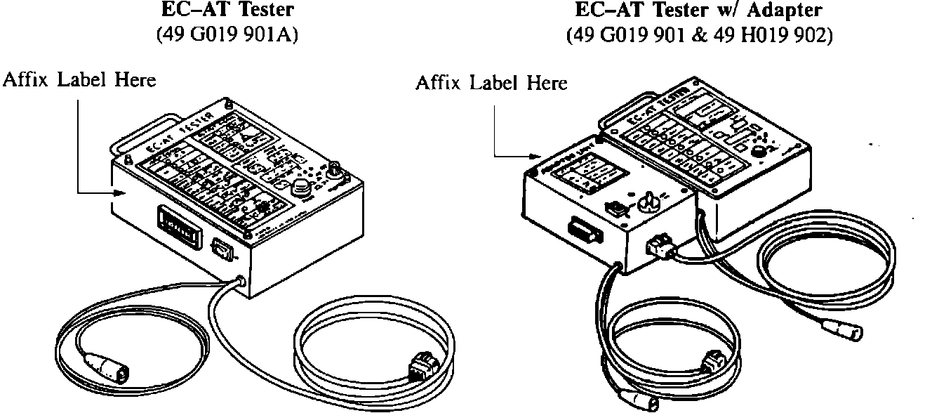
When using the EC-AT Tester, it is critical that the 6-pin connector (with ground) that is located on the bottom left-hand corner of the EC-AT Tester body is never connected at the same time an adapter harness is being used.
Symptom codes should be retrieved from the Control Unit* first using the 6-pin connector; after disconnecting the 6-pin connector, the adapter harness can be used for further diagnosis.
* "Control Unit" refers to EC-AT Control Unit, except for 1990 626/MX-6 non-Turbo. For these models, the EC-AT Control Unit is incorporated into the Engine Control Unit.
REPAIR PROCEDURE
Please affix the attached label on the left side of the EC-AT Tester body, to the left of the adapter harness connector. On versions with the adapter, affix the label on the top panel of the adapter.
Category Applicable Model/s
ST All Models
w/ EC-AT
Subject PROPER EC-AT CONNECTION
Bulletin No. 002/90
Issued 8/1/90
Revised
DESCRIPTION
When using the EC-AT Tester, it is critical that the 6-pin connector (with ground) that is located on the bottom left-hand corner of the EC-AT Tester body is never connected at the same time an adapter harness is being used.
Symptom codes should be retrieved from the Control Unit* first using the 6-pin connector; after disconnecting the 6-pin connector, the adapter harness can be used for further diagnosis.
* "Control Unit" refers to EC-AT Control Unit, except for 1990 626/MX-6 non-Turbo. For these models, the EC-AT Control Unit is incorporated into the Engine Control Unit.
REPAIR PROCEDURE
Please affix the attached label on the left side of the EC-AT Tester body, to the left of the adapter harness connector. On versions with the adapter, affix the label on the top panel of the adapter.
Factory Service Tools
Use the Manual With the Right Hardware
Pair factory procedures with proven DIY tools so the instructions are easier to execute.
Disclosure: Verified tool recommendations may earn an affiliate commission at no cost to you.
When to See a Mechanic
Stop DIY work and contact a certified mechanic immediately if any of the following apply:
- • You smell fuel, burning insulation, or see smoke.
- • Brakes feel soft, pull hard to one side, or make grinding noises.
- • The engine overheats, stalls repeatedly, or misfires under load.
- • You are missing required tools, torque specs, or safe lifting equipment.
- • You are not confident in the next step or safety outcome.