
Safety Warning
DIY auto repair can cause serious injury, fire, or vehicle damage. These guides are for informational purposes only. Always follow OEM torque specs, wear PPE, and consult a certified mechanic if you are unsure. You are solely responsible for your safety.
2004 Land Rover Freelander (LN) V6-2.5LFACTORY OEM SERVICE PROCEDURE
Remove
Remove
1. Make the SRS system safe.
2. Remove carpet.
3. Remove engine acoustic cover.
4. Remove windscreen washer reservoir.
5. Pull reservoir harness and washer tubes into engine bay.

6. Remove nut and release earth header from RH inner wing.
7. Disconnect multiplug from ABS modulator.
8. Disconnect multiplug from RH ABS speed sensor and release harness from clips.
9. Disconnect 2 multiplugs from RH headlamp and headlamp levelling motor.

10. Disconnect multiplugs from horn, refrigerant pressure sensor and compressor.
11. Remove jack from holder in engine bay.

12. Disconnect multiplug from brake fluid low level indicator switch.
13. Disconnect multiplug from bonnet switch.
14. Remove bolt and 2 nuts securing PAS and coolant reservoir support bracket and position aside.
15. Release 5 harness retaining clips.
16. Release front screen wash tube from harness and position aside.
17. Remove nut securing earth header to bulk head and remove earth header.
18. With assistance feed harness through bulk head into vehicle.
19. Remove battery carrier.
20. Remove 3 cable ties and release bonnet release cable from harness.

21. Disconnect multiplug from cooling fan pack and 2 multiplugs from cooling fans.
22. Release 4 clips securing harness to cooling fans and release harness from cooling fans.

23. Disconnect 2 multiplugs from LH headlamp and headlamp levelling motor.
24. Disconnect multiplug from harness.
25. Remove nut securing LH earth header and release header.
26. Disconnect multiplug from front LH ABS speed sensor.

27. Disconnect Lucar connector from starter motor.
28. Models with cruise control: Disconnect multiplug from cruise control vacuum pump.
29. Release 5 harness retaining clips.
30. Disconnect 2 engine harness to main harness multiplugs.

31. Release 5 Allen screws securing 'E' box cover to 'E' box.
32. Remove 'E' box cover
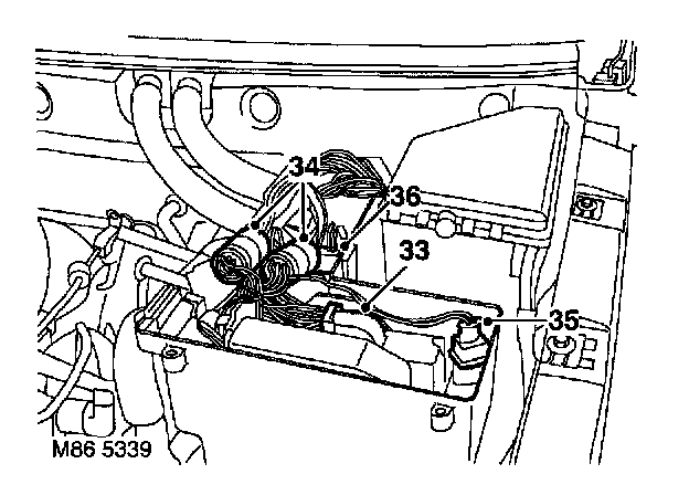
33. Automatic gearbox only: Disconnect multiplug from automatic gearbox ECU.
34. Disconnect 2 engine harness to main harness multiplugs.
35. Disconnect 'E' box temperature sensor multiplug.
36. Disconnect E box cooling fan multiplug.
37. Remove fuse box cover.

38. Remove 2 bolts securing battery connections to fuse box and disconnect multiplug from fuse box.
39. Remove 3 nuts securing fuse box to brackets.
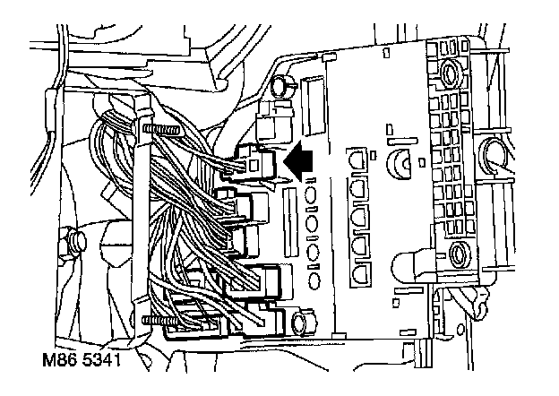
40. Disconnect 6 multiplugs from the underside of fusebox.

41. Disconnect multiplug from inertia switch.
42. Release 2 fixings securing harness to LH side of engine bay.
43. Remove air intake plenum.

44. Disconnect multiplug from wiper motor and pull into engine bay.
45. With assistance pull main harness into vehicle interior.

46. Remove 6 screws securing front mud flaps and remove mud flaps.
47. Release rear edges of front wheel arch liners.

48. Release side repeater lamps, disconnect multiplugs and remove lamps.

49. Remove 3 bolts from passenger compartment fuse box and pull fuse box forward.
50. Release and disconnect multiplug from RH 'A' post.
51. Disconnect coaxial cable.
52. Release relays from fuse box bracket.
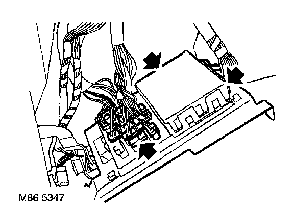
53. Release fuse box, disconnect 11 multiplugs and remove fuse box.

54. Disconnect multiplug from steering column switch.
55. Release harness clip from steering column.

56. Disconnect multiplug from throttle position sensor.
57. Disconnect multiplugs from brake light switch and brake pedal position switch.

58. Disconnect multiplug from airbag ECU.
59. Remove airbag ECU securing bolt and release earth lead.

60. Remove nut from earth header and release header from floor tunnel.

61. Disconnect heated oxygen sensor multiplug.
62. Automatic gearbox only: Disconnect multiplugs from gear selector.
63. Disconnect multiplug from accelerometer.
64. Manual gearbox only: Disconnect multiplug from gear lever hill descent switch.
65. Disconnect Lucar from handbrake switch.
66. Release 2 relays from bracket and remove bracket.
67. Release 4 clips securing harness to air ducting
68. Remove nut from rear heater ducting and remove ducting.

69. Remove 4 nuts securing steering column to bracket and lower column.
70. Remove face level vent ducting to access main harness clips.

71. Disconnect multiplug from window lift ECU.
72. Remove nut securing earth header to RH 'A' post and release header.

73. Release multiplugs and earth header from LH lower 'A' post.

74. Release all harness clips from interior of vehicle.

75. Release and disconnect multiplugs from base of 'B/C' posts.
76. Remove luggage compartment carpet.

77. Remove 6 screws from fuel pump access cover and remove cover.
78. Disconnect multiplug from fuel pump.

79. Release both rear ABS speed sensor harnesses and disconnect multiplugs.
80. Pull harness into vehicle interior.

81. Release and disconnect rear window lift and wash/wipe relays.

82. Disconnect 3 multiplugs from tail door harness.
83. Disconnect rear screen washer tube.
84. Disconnect multiplug from towing electrics.
85. Remove nut from RH rear earth header and release header.

86. Remove 3 Torx screws securing RH tail lamp to body.
87. Disconnect multiplugs and remove tail lamp.

88. Disconnect multiplugs from LH tail lamp.
89. Remove nut from LH rear earth header and release header.

90. Remove 4 screws from rear bumper lamps, release lamps and disconnect multiplugs.
91. Release harness clips and pull harness into luggage compartment.
92. Release main harness retaining clips and pull harness into vehicle interior.
93. Remove main harness.
Factory Service Tools
Use the Manual With the Right Hardware
Pair factory procedures with proven DIY tools so the instructions are easier to execute.
Disclosure: Verified tool recommendations may earn an affiliate commission at no cost to you.
When to See a Mechanic
Stop DIY work and contact a certified mechanic immediately if any of the following apply:
- • You smell fuel, burning insulation, or see smoke.
- • Brakes feel soft, pull hard to one side, or make grinding noises.
- • The engine overheats, stalls repeatedly, or misfires under load.
- • You are missing required tools, torque specs, or safe lifting equipment.
- • You are not confident in the next step or safety outcome.
Rather have a pro handle this?
A certified mobile mechanic comes to your home or office. They bring the tools, you stay comfortable. No tow truck, no waiting room, no surprises.
Comes to youSame-day available12-month warranty
Get a Free QuoteNo obligation. See pricing before you book.