
Safety Warning
DIY auto repair can cause serious injury, fire, or vehicle damage. These guides are for informational purposes only. Always follow OEM torque specs, wear PPE, and consult a certified mechanic if you are unsure. You are solely responsible for your safety.
2012 Kia Optima L4-2.4LFACTORY OEM SERVICE PROCEDURE
Repair Procedures
Inspection
Smart Key Unit
- Refer to the BE group - inspection / self diagnosis with GDS.
Smart Key Switch
- Refer to the BE group - inspection / self diagnosis with GDS.
Antenna
- Refer to the BE group - inspection / self diagnosis with GDS.
Trunk Lid Open Switch
1. Check for continuity between the Trunk lid open switch terminals.

2. If continuity is not specified, inspect the switch

Removal
NOTE:
- Take care not to scratch the crash pad and related parts
Smart key unit
1. Disconnect the negative(-) battery terminal.
2. Remove the glove box.
3. Remove the smart key unit (A) after disconnecting the connector and loosening the mounting nuts (2EA).

4. Remove the smart key unit (A) with bracket (B) after loosening the mounting nuts, shear bolts (C).
[CANADA]

CAUTION:
Do not reuse the shear bolts. When installing the new shear bolts to the smart key unit, tighten the shear bolts until its head is cut off.
RF Receiver
NOTE:
- Take care not to scratch the crash pad and related parts
1. Disconnect the negative(-) battery terminal.
2. Remove the glove box.
3. Remove the RF receiver (A) after loosening the mounting nuts (1EA) and disconnecting the connector.

Interior 1 Antenna
NOTE:
- Take care not to scratch the crash pad and related parts
1. Disconnect the negative(-) battery terminal.
2. Remove the heater control unit (A) after removing the screws.

3. Remove the interior 1 antenna (A) after disconnecting the connector and loosening the mounting nuts (2EA).

Interior 2 Antenna
1. Disconnect the negative(-) battery terminal.
2. Remove the center console rear cover (A).

NOTE:
Take care not to damage and scratch the console rear cover and its related parts.
Apply the protective tapes to the console rear cover and its related parts.
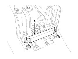
3. Disconnect the interior 2 antenna connector located at the console rear side, then remove the interior 2 antenna (A) after loosening screws (2EA).
Trunk Antenna
1. Disconnect the negative(-) battery terminal.
2. Remove the trunk transverse trim.
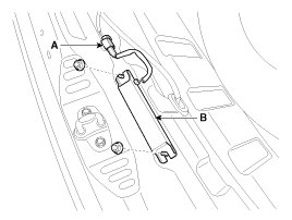
3. Disconnect the trunk antenna connector (A) and remove the trunk antenna (B) after loosening nut (2EA).
Exterior Bumper Antenna
1. Disconnect the negative(-) battery terminal.
2. Remove the rear bumper.
3. Disconnect the antenna connector (B) and remove the exterior bumper antenna (A) after loosening the screws (2EA).

Buzzer
1. Disconnect the negative(-) battery terminal.
2. Remove the left side wheel guard.
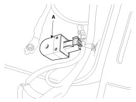
3. Remove the external buzzer (A) after disconnecting the connector.
Door Outside Handle
1. Disconnect the negative (-) battery terminal.
2. Remove the front door module.
3. Remove the hole plug (B).
4. After loosening the mounting bolt, then remove the outside handle cover (A).
Tightening torque:
0.7 - 0.5 N.m (0.07 - 0.1 kgf.m, 1.0 - 0.7 lb-ft)

5. Remove the outside handle (A) by sliding it rearward.

6. Disconnect the outside handle connector (A).

Trunk lid open switch
1. Disconnect the negative(-) battery terminal.
2. Remove the trunk door trim.
3. Disconnect the trunk lid open switch connector (A).

4. Remove the trunk open switch (A) from the trunk garnish after pressing the clips (B).

Installation
Smart Key Unit
1. Install the smart key unit.
2. Install the smart key unit mounting nuts and bolts and connector.
3. Install the glove box housing.
4. Install the glove box.
5. Install the negative (-) battery terminal and check the smart key system.
RF Receiver
1. Install the RF receiver.
2. Install the glove box housing.
3. Install the glove box.
4. Install the negative (-) battery terminal and check the smart key system.
Interior 1 Antenna
1. Install the interior 1 antenna.
2. Install the heater control unit
3. Install the negative (-) battery terminal and check the smart key system.
Interior 2 Antenna
1. Install the interior 2 antenna.
2. Install the console rear cover after connecting the connector.
3. Install the negative (-) battery terminal and check the smart key system.
Trunk Antenna
1. Install the trunk antenna.
2. Install the trunk trim.
3. Install the negative (-) battery terminal and check the smart key system.
Exterior Bumper Antenna
1. Install the exterior bumper antenna.
2. Install the rear bumper.
3. Install the negative (-) battery terminal and check the smart key system.
Buzzer
1. Install the buzzer.
2. Install the left side wheel guard.
3. Install the negative (-) battery terminal and check the smart key system.
Trunk Lid Open Switch
1. Install the trunk lid open switch.
2. Install the trunk trim.
3. Install the negative (-) battery terminal and check the smart key system.
Door Outside Handle
1. Install the outside handle.
2. Install the door trim.
3. Install the negative (-) battery terminal and check the smart key system.
Factory Service Tools
Use the Manual With the Right Hardware
Pair factory procedures with proven DIY tools so the instructions are easier to execute.
Disclosure: Verified tool recommendations may earn an affiliate commission at no cost to you.
When to See a Mechanic
Stop DIY work and contact a certified mechanic immediately if any of the following apply:
- • You smell fuel, burning insulation, or see smoke.
- • Brakes feel soft, pull hard to one side, or make grinding noises.
- • The engine overheats, stalls repeatedly, or misfires under load.
- • You are missing required tools, torque specs, or safe lifting equipment.
- • You are not confident in the next step or safety outcome.
Rather have a pro handle this?
A certified mobile mechanic comes to your home or office. They bring the tools, you stay comfortable. No tow truck, no waiting room, no surprises.
Comes to youSame-day available12-month warranty
Get a Free QuoteNo obligation. See pricing before you book.