
Safety Warning
DIY auto repair can cause serious injury, fire, or vehicle damage. These guides are for informational purposes only. Always follow OEM torque specs, wear PPE, and consult a certified mechanic if you are unsure. You are solely responsible for your safety.
2010 Kia Optima V6-2.7LFACTORY OEM SERVICE PROCEDURE
Instruments - Trip Computer Display Errors
Model: Optima [MG]
Group: Body Electrical System(92)
Number: KT2009111701
Date: Tuesday, November 17, 2009
Area: N. America
Subject
PCM UPGRADE: Trip Computer Improvement (2.7L
engine) with Auto Transmission (GEN - 032)
- Description

This bulletin provides information related to the PCM software upgrade of 2009~2010 Model Year Optima (MG) equipped with 2.7L engines and automatic transmission produced prior to 8/31/2009, which may experience an average fuel consumption display error. Some customers may complain the average fuel consumption on the IP cluster does not work correctly.


To correct this condition, the PCM should be reprogrammed using the GDS download as described in this bulletin.

ROM ID TABLE:
- Verify the vehicle is affected, be sure to check the version of the vehicle's control unit ROM ID with reference to the ROM ID Information Table.
- Effective Vehicle Information
AFFECTED PRODUCTION RANGE:
2009~2010 Optima (MG) vehicles with 2.7L engine produced prior to 8/31/2009.
- Service Procedure
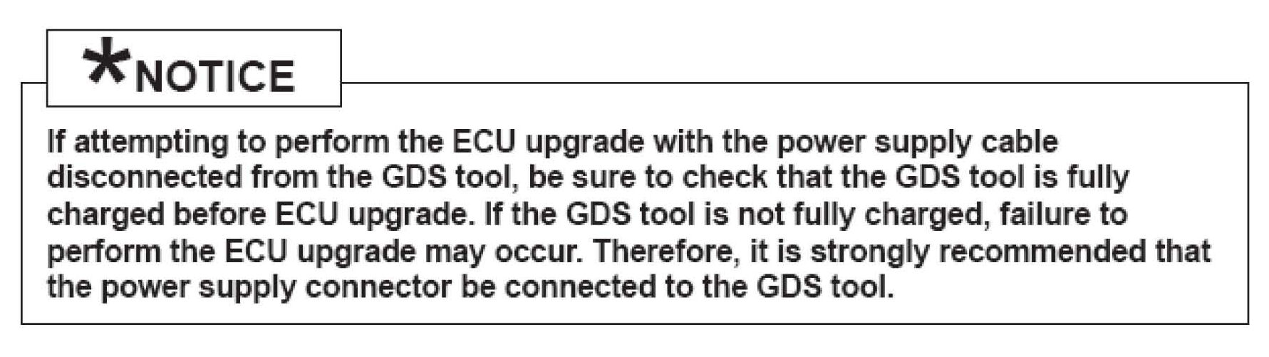
1. Connect the power supply cable to the GDS tool.

2. Connect the USB cable between the VCI and the GDS tool.
3. Connect the Main 16-pin DLC cable (GHDM - 241000) to the VCI.

4. Connect the Main 16-pin DLC cable (GHDM - 241000) to the OBD-II connector, located under the driver's side of the instrument panel.

5. With the ignition key ON, turn ON the VCI and GDS tool. Access the GDS vehicle identification number (VIN) screen and configure the vehicle using the VIN AUTO DETECT Function.
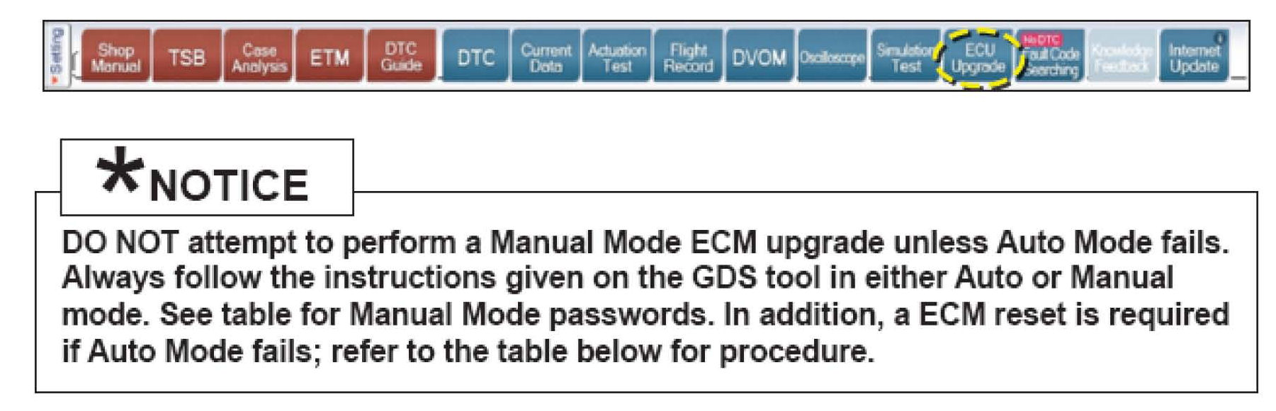
6. Once back at the GDS Main Screen, select ECM upgrade from the bottom right-hand corner. Next select Auto Mode, Engine.
Perform the ECM upgrade in accordance with normal GDS tool ECM upgrade procedures.

* MANUAL MODE ECM UPGRADE PASSWORDS:
* Do NOT perform Manual Mode ECU upgrade unless Auto Mode fails.
7. When the GDS tool reports that the ECM upgrade has been successfully completed, click OK, turn OFF the ignition key, and wait at least 10 seconds before attempting to start the engine.
8. Check for Diagnostic Trouble Codes using the GDS and erase any DTCs stored in the Engine and Transaxle control modules (EPS, ESC, TPMS).

WARRANTY CLAIM INFORMATION:
Group: Body Electrical System(92)
Number: KT2009111701
Date: Tuesday, November 17, 2009
Area: N. America
Subject
PCM UPGRADE: Trip Computer Improvement (2.7L
engine) with Auto Transmission (GEN - 032)
- Description
This bulletin provides information related to the PCM software upgrade of 2009~2010 Model Year Optima (MG) equipped with 2.7L engines and automatic transmission produced prior to 8/31/2009, which may experience an average fuel consumption display error. Some customers may complain the average fuel consumption on the IP cluster does not work correctly.
To correct this condition, the PCM should be reprogrammed using the GDS download as described in this bulletin.
ROM ID TABLE:
- Verify the vehicle is affected, be sure to check the version of the vehicle's control unit ROM ID with reference to the ROM ID Information Table.
- Effective Vehicle Information
AFFECTED PRODUCTION RANGE:
2009~2010 Optima (MG) vehicles with 2.7L engine produced prior to 8/31/2009.
- Service Procedure
1. Connect the power supply cable to the GDS tool.
2. Connect the USB cable between the VCI and the GDS tool.
3. Connect the Main 16-pin DLC cable (GHDM - 241000) to the VCI.
4. Connect the Main 16-pin DLC cable (GHDM - 241000) to the OBD-II connector, located under the driver's side of the instrument panel.
5. With the ignition key ON, turn ON the VCI and GDS tool. Access the GDS vehicle identification number (VIN) screen and configure the vehicle using the VIN AUTO DETECT Function.
6. Once back at the GDS Main Screen, select ECM upgrade from the bottom right-hand corner. Next select Auto Mode, Engine.
Perform the ECM upgrade in accordance with normal GDS tool ECM upgrade procedures.
* MANUAL MODE ECM UPGRADE PASSWORDS:
* Do NOT perform Manual Mode ECU upgrade unless Auto Mode fails.
7. When the GDS tool reports that the ECM upgrade has been successfully completed, click OK, turn OFF the ignition key, and wait at least 10 seconds before attempting to start the engine.
8. Check for Diagnostic Trouble Codes using the GDS and erase any DTCs stored in the Engine and Transaxle control modules (EPS, ESC, TPMS).
WARRANTY CLAIM INFORMATION:
Factory Service Tools
Use the Manual With the Right Hardware
Pair factory procedures with proven DIY tools so the instructions are easier to execute.
Disclosure: Verified tool recommendations may earn an affiliate commission at no cost to you.
When to See a Mechanic
Stop DIY work and contact a certified mechanic immediately if any of the following apply:
- • You smell fuel, burning insulation, or see smoke.
- • Brakes feel soft, pull hard to one side, or make grinding noises.
- • The engine overheats, stalls repeatedly, or misfires under load.
- • You are missing required tools, torque specs, or safe lifting equipment.
- • You are not confident in the next step or safety outcome.