
Safety Warning
DIY auto repair can cause serious injury, fire, or vehicle damage. These guides are for informational purposes only. Always follow OEM torque specs, wear PPE, and consult a certified mechanic if you are unsure. You are solely responsible for your safety.
2008 Kia Optima L4-2.4LFACTORY OEM SERVICE PROCEDURE
Alignment: Service and Repair
WHEEL ALIGNMENT
When using commercially available computerized four wheel alignment equipment (caster, camber, toe) to inspect the front wheel alignment, always position the car on a level surface with the front wheels facing straight ahead.
Prior to inspection, make sure that the front suspension and steering system are in normal operating condition and that the wheels and tires face straight ahead and the tires are inflated to the specified pressure.
TOE
Toe is a measurement of how much the front of the wheels are turned in or out from the straight-ahead position.


When the wheels are turned in toward the front of the vehicle, toe is positive (+) (toe in). When the wheels are turned out toward the front of the vehicle, toe is negative(-) (toe out). Toe is measured in degrees, from side to side, and totaled.
[FRONT]
Toe-in(B-A or angle a+b) is adjusted by turning the tie rod turnbuckles. Toe-in on the left front wheel can be reduced by turning the tie rod toward the rear of the car. Toe- in change is adjusted by turning the tie rods for the right and left heels simultaneously at the same amount as follows.
Standard value :
Toe-in (B-A) mm (in) : 0 ± 2 (0 ± 0.0787)
NOTE:
- Toe-in adjustment should be made by turning the right and left tie rods at the same amount.
- When adjusting toe-in, loosen the outer bellows clip to prevent twisting the bellows.
- After the adjustment, tighten the tie rod end lock nuts firmly and reinstall the bellows clip.
- Adjust each toe-in to be the range of ±1mm.
Tie rod(A) Specified torque Nm (kgf.m, lb-ft) :
49.0 - 53.9 (5.0 - 5.5, 36.2 - 39.8)

[REAR]
Standard value :
Toe-in (B-A) mm (in) : 2.0 ± 2 (0.0787 ± 0.0787)
Adjust the toe-in by turning the cambolt of the assist arm.
Left cambolt : Clockwise -> toe-in
Right cambolt : Clockwise -> toe-out
The variation of toe by a rotation of the cambolt :
About 3.2 mm (0.126 in)
CAUTION:
- Each toe should be within ±1 mm (± 0.039 in).
If the difference between right and left is not within +2mm (0.079 in), repeat adjustment.
- After adjusting the cambolt, tighten the nut to the specified torque.

Specified torque
78.8 - 98.1 Nm (8.0 - 10.0 kgf.m, 57.9 - 75.3 lb-ft)
CAMBER
[FRONT]
Camber is the inward or outward tilting of the wheels at the top.


When the wheel tilts out at the top, then the camber is positive (+).
When the wheel tilts in at the top, then the camber is negative(-).
Standard value : -0.5° ± 30'
Difference between right and left angle is within 0° 30'
NOTE:
Camber is pre-set at the factory and doesn't need to be adjusted. If the camber is not within the standard value, replace the bent or damaged parts.
[REAR]
Standard value : -1°00' ± 30'
Difference between right and left angle is within 0° 30'

Adjust the camber by turning the cambolt of the rear upper arm.
Left cambolt : Clockwise -> camber(+)
Right cambolt : Clockwise ->camber(-)
The variation of camber by a rotation of the cambolt :
About 0°8'35''
CASTER
Caster is the tilting of the strut axis either forward or backward from vertical. A backward tilt is positive (+) and a forward tilt is negative (-).
Caster is pre-set at the factory and doesn't need to be adjusted. If the caster is not within the standard value, replace the bent or damaged parts.
Caster : 4.74° ± 30' (to ground), 4.91° (to body)

NOTE:
- The worn loose or damaged parts of the front suspension assembly must be replaced prior to measuring front wheel alignment.
- Caster are pre-set to the specified value at the factory and don't need to be adjusted.
- If the caster are not within specifications, replace bent or damaged parts.
- The difference of left and right wheels about the the caster must be within the range of 0° ± 30'.
WHEEL RUNOUT
1. Jack up the vehicle and support it with jack stands.
2. Measure the wheel runout with a dial indicator as illustrated.
3. Replace the wheel if the wheel runout exceeds the limit.


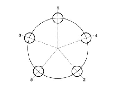
WHEEL NUT TIGHTENING
1. Tightening torque.
Tightening torque Nm (kgf.m, lb-ft) :
88.3 - 107.9 (9 - 11, 65.1 - 79.5)
CAUTION:
When using an impact gun, final tightening torque should be checked using a torque wrench.
2. Tightening order.
Check the torque again after tightening the wheel nuts diagonally.

Factory Service Tools
Use the Manual With the Right Hardware
Pair factory procedures with proven DIY tools so the instructions are easier to execute.
Disclosure: Verified tool recommendations may earn an affiliate commission at no cost to you.
When to See a Mechanic
Stop DIY work and contact a certified mechanic immediately if any of the following apply:
- • You smell fuel, burning insulation, or see smoke.
- • Brakes feel soft, pull hard to one side, or make grinding noises.
- • The engine overheats, stalls repeatedly, or misfires under load.
- • You are missing required tools, torque specs, or safe lifting equipment.
- • You are not confident in the next step or safety outcome.
Rather have a pro handle this?
A certified mobile mechanic comes to your home or office. They bring the tools, you stay comfortable. No tow truck, no waiting room, no surprises.
Comes to youSame-day available12-month warranty
Get a Free QuoteNo obligation. See pricing before you book.