
Safety Warning
DIY auto repair can cause serious injury, fire, or vehicle damage. These guides are for informational purposes only. Always follow OEM torque specs, wear PPE, and consult a certified mechanic if you are unsure. You are solely responsible for your safety.
2005 Kia Optima L4-2.4LFACTORY OEM SERVICE PROCEDURE
Body/Frame - Revised Front Subframe Service Procedure
Model Optima [MS]
Group Suspension System (21)
Number KT2009041701
Date Wednesday, June 10, 2009
Area N.America
Subject
2001-2005 Optima (MS) Subframe Revised Service Procedure (General Information - 026)
- Description
During a service procedure that requires the subframe to be removed from a 2001-2005 Optima (MS) (V-6 or I-4), an improved service procedure has been developed to enhance service efficiency. Prior to the release of this service bulletin, the 2001-2005 service manual required the removal of the rack & pinion with the subframe. The improved procedure outlined in this TSB reflects the removal of the subframe with the rack & pinion retained with the vehicle. The modification of this service procedure includes a two (2) wheel alignment within the allowed labor time.
SERVICE PROCEDURE:
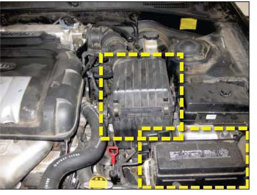
1. Place the vehicle on a hoist and record radio presets. Open the hood and remove the battery from the vehicle. Remove the air cleaner from the vehicle.
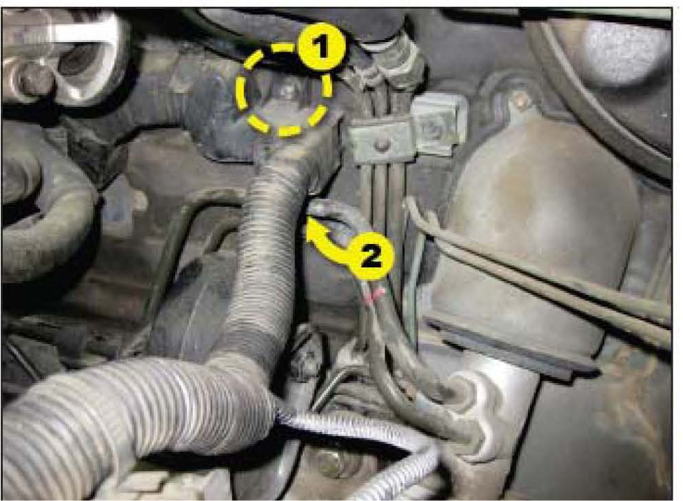
2. Remove the two (2) main wiring mounting nuts and allow sufficient free-play of the main harness for the remainder of this procedure.
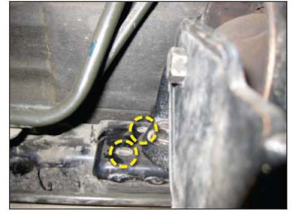
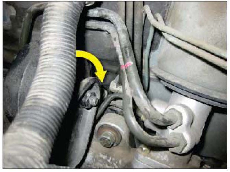
3. Remove the rear transmission mounting bolts, remove the rear transmission mount. Install an upper engine / transmission support fixture.
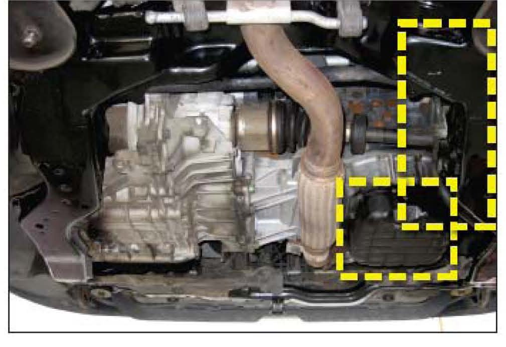
4. Raise the vehicle to gain access to the underbody. Remove the two (2) undercovers. Remove the exhaust down pipes.
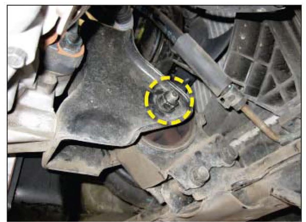
5. Remove the lower front transmission mount bolt.
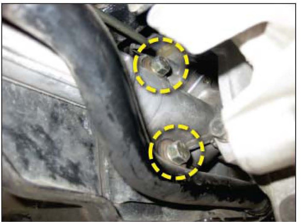
6. Remove the two (2) right-hand side rack & pinion mounting bolts.
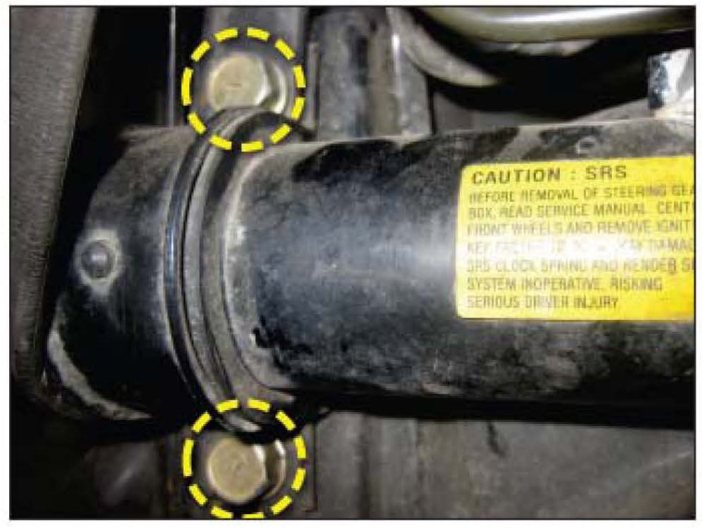
7. Remove the two (2) left-hand side rack and pinion (2) mounting bolts.
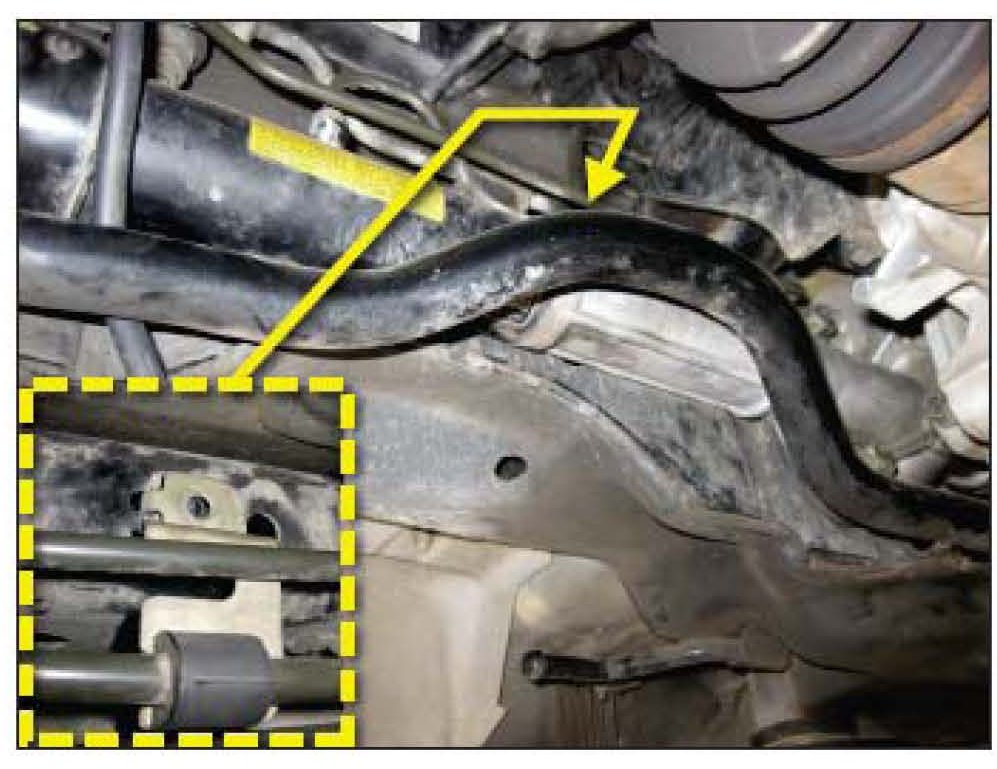
8. Remove the upper power steering line mounting bolt.
NOTICE
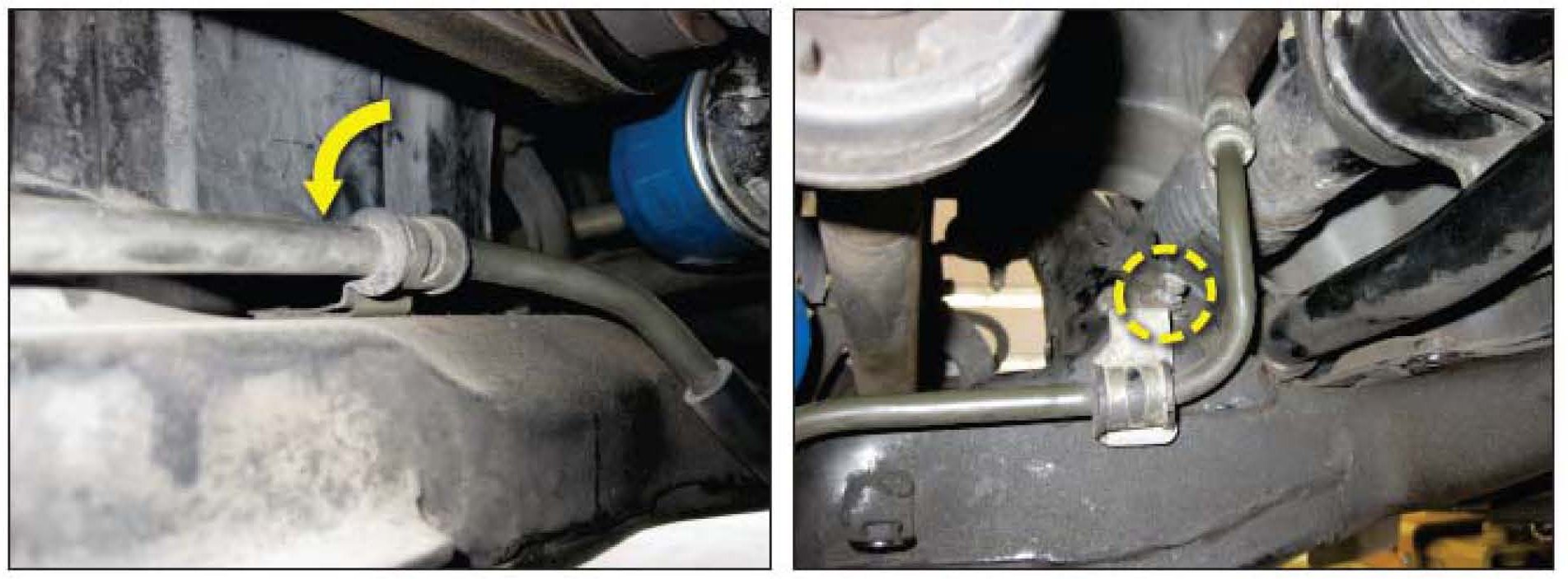
9. Remove the remaining power steering line mounting line bolts.
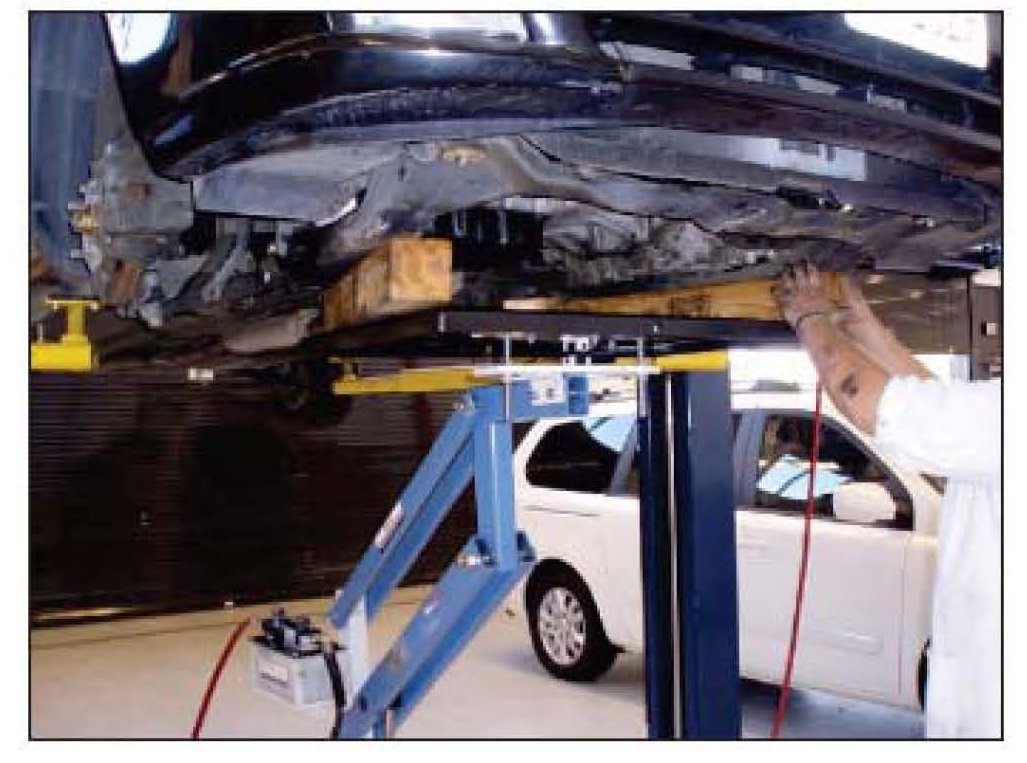
10. Support the subframe with a transmission / engine fixture support. Remove the four subframe brackets and bolts from all 4 corners. Remove the front wheels.
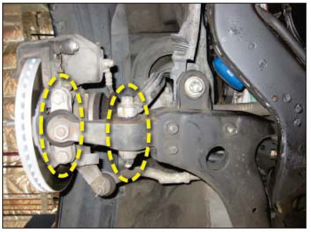
11. Remove both the left / right lower ball joint bolts and lower strut attachment bolts.
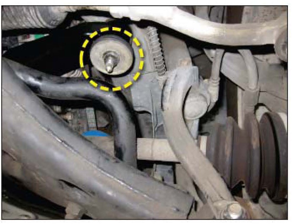
12. Remove the two (2) upper subframe mounting nuts and lower the subframe from the vehicle, while retaining the rack & pinion in the vehicle.
13. Install in reverse order of removal, reference the 2001- 2005 Optima Service Manuals or KGIS for critical torque applications.
14. Perform a two-wheel alignment. Reset Customer Radio Presets.
15. If installing this subframe as part of Safety Recall Campaign SC 075, a safety recall campaign sticker must be installed (see Technical Service Bulletin SC 075, step 14).
Group Suspension System (21)
Number KT2009041701
Date Wednesday, June 10, 2009
Area N.America
Subject
2001-2005 Optima (MS) Subframe Revised Service Procedure (General Information - 026)
- Description
During a service procedure that requires the subframe to be removed from a 2001-2005 Optima (MS) (V-6 or I-4), an improved service procedure has been developed to enhance service efficiency. Prior to the release of this service bulletin, the 2001-2005 service manual required the removal of the rack & pinion with the subframe. The improved procedure outlined in this TSB reflects the removal of the subframe with the rack & pinion retained with the vehicle. The modification of this service procedure includes a two (2) wheel alignment within the allowed labor time.
SERVICE PROCEDURE:
1. Place the vehicle on a hoist and record radio presets. Open the hood and remove the battery from the vehicle. Remove the air cleaner from the vehicle.
2. Remove the two (2) main wiring mounting nuts and allow sufficient free-play of the main harness for the remainder of this procedure.
3. Remove the rear transmission mounting bolts, remove the rear transmission mount. Install an upper engine / transmission support fixture.
4. Raise the vehicle to gain access to the underbody. Remove the two (2) undercovers. Remove the exhaust down pipes.
5. Remove the lower front transmission mount bolt.
6. Remove the two (2) right-hand side rack & pinion mounting bolts.
7. Remove the two (2) left-hand side rack and pinion (2) mounting bolts.
8. Remove the upper power steering line mounting bolt.
NOTICE
9. Remove the remaining power steering line mounting line bolts.
10. Support the subframe with a transmission / engine fixture support. Remove the four subframe brackets and bolts from all 4 corners. Remove the front wheels.
11. Remove both the left / right lower ball joint bolts and lower strut attachment bolts.
12. Remove the two (2) upper subframe mounting nuts and lower the subframe from the vehicle, while retaining the rack & pinion in the vehicle.
13. Install in reverse order of removal, reference the 2001- 2005 Optima Service Manuals or KGIS for critical torque applications.
14. Perform a two-wheel alignment. Reset Customer Radio Presets.
15. If installing this subframe as part of Safety Recall Campaign SC 075, a safety recall campaign sticker must be installed (see Technical Service Bulletin SC 075, step 14).
Factory Service Tools
Use the Manual With the Right Hardware
Pair factory procedures with proven DIY tools so the instructions are easier to execute.
Disclosure: Verified tool recommendations may earn an affiliate commission at no cost to you.
When to See a Mechanic
Stop DIY work and contact a certified mechanic immediately if any of the following apply:
- • You smell fuel, burning insulation, or see smoke.
- • Brakes feel soft, pull hard to one side, or make grinding noises.
- • The engine overheats, stalls repeatedly, or misfires under load.
- • You are missing required tools, torque specs, or safe lifting equipment.
- • You are not confident in the next step or safety outcome.
Rather have a pro handle this?
A certified mobile mechanic comes to your home or office. They bring the tools, you stay comfortable. No tow truck, no waiting room, no surprises.
Comes to youSame-day available12-month warranty
Get a Free QuoteNo obligation. See pricing before you book.