
Safety Warning
DIY auto repair can cause serious injury, fire, or vehicle damage. These guides are for informational purposes only. Always follow OEM torque specs, wear PPE, and consult a certified mechanic if you are unsure. You are solely responsible for your safety.
2003 Kia Sorento V6-3.5LFACTORY OEM SERVICE PROCEDURE
Throttle Position Sensor: Testing and Inspection
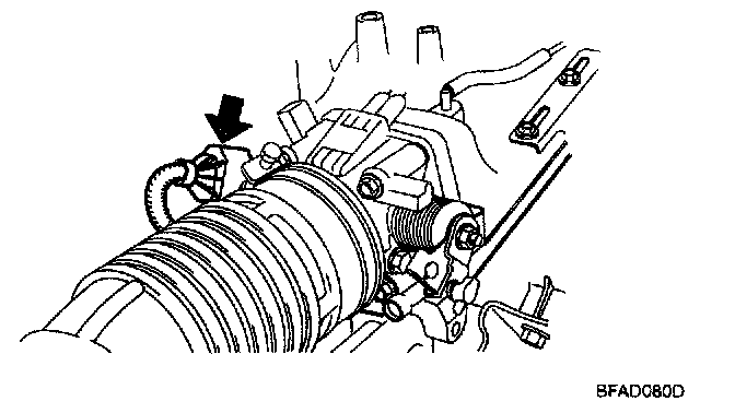
Throttle Position Sensor (TPS)
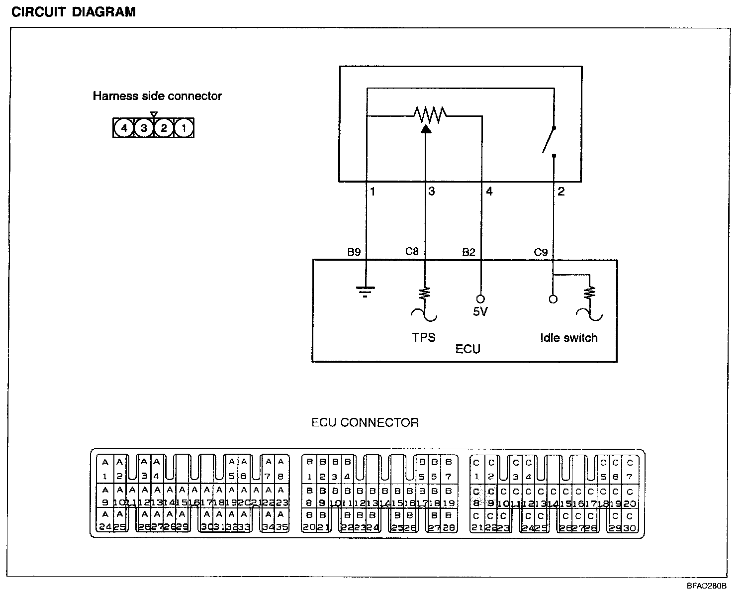
The TPS is a variable resistor type that rotates with the throttle shaft to sense the throttle valve angle. As the throttle shaft rotates, the output voltage of the TPS changes. The ECU detects the throttle valve opening based on this voltage change.
Circuit Diagram:
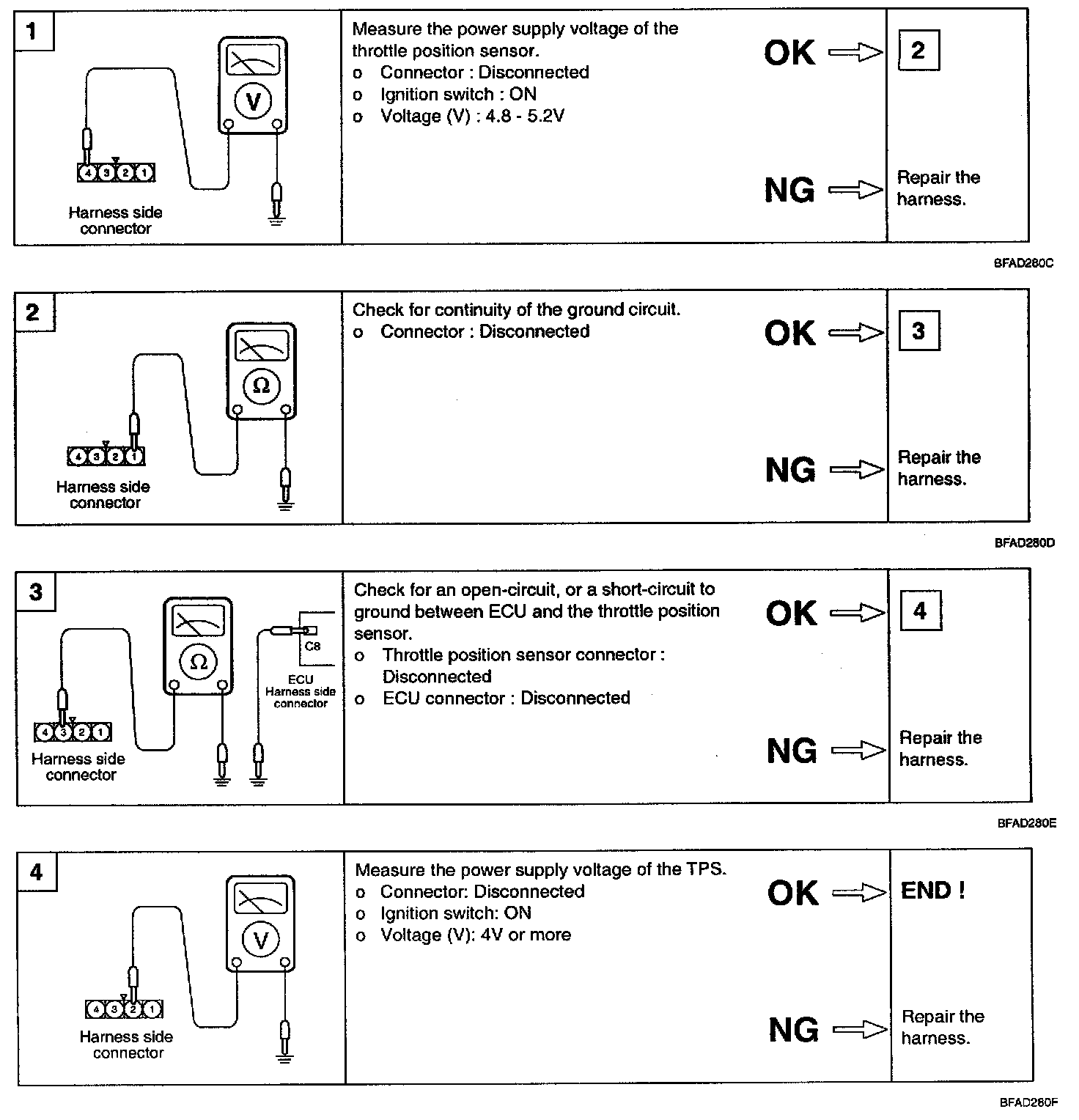
Harness Inspection Procedures:
Troubleshooting Hints
The TPS signal is important in the control of the automatic transaxle. Shift shock and other trouble will occur if the sensor is faulty.
Using Hi-Scan (Pro):

Using voltmeter
1. Disconnect the throttle position sensor connector.
2. Measure resistance between terminal 1 (sensor ground) and terminal 4 (sensor power).
Standard value: 3.5 - 6.5 kOhm
3. Connect a pointer type ohmmeter between terminal 1 (sensor ground) and terminal 3 (sensor output).
4. Operate the throttle valve slowly from the idle position to the full open position and check that the resistance changes smoothly in proportion with the throttle valve opening angle.

5. If the resistance is out of specification, or fails to change smoothly, replace the throttle position sensor.
Tightening torque:
TPS Sensor: 1.5 - 2.5 Nm (15 - 25 kg.cm, 1.1 - 1.8 lb.ft)
Sensor Checking (Idle Switch)
Using Hi-Scan (Pro):

Using voltmeter
1. Disconnect the throttle position sensor connector.
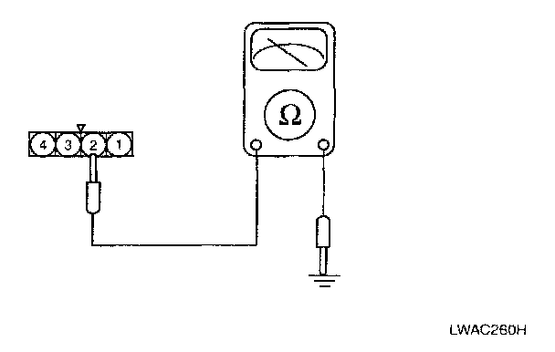
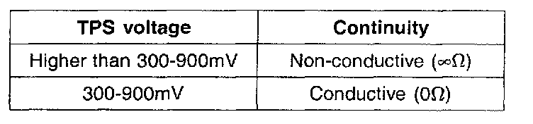
2. Check the continuity between terminal 3 and sensor ground.
3. If out of specification, replace the throttle position sensor.
Inspection
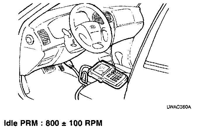
1. Connect a HI-SCAN (PRO) to the data link connector.
NOTE: Before inspecting the TPS, verify the basic idle speed is as specified.
2. If a HI-SCAN (PRO) is not used, connect a digital type voltmeter between ground and TPS output terminal.
3. Turn the ignition switch to the ON position(do not start engine) and check that TPS output voltage is as specified. If a HI-SCAN (PRO) is used, read the TPS voltage.
4. If it is out of specification, loosen TPS mounting screws and adjust by turning the TPS.
NOTE:
- Turning the TPS clockwise increases the output voltage.
- Tighten the screws securely after adjustment.
5. Turn the ignition switch to the OFF position.
Factory Service Tools
Use the Manual With the Right Hardware
Pair factory procedures with proven DIY tools so the instructions are easier to execute.
Disclosure: Verified tool recommendations may earn an affiliate commission at no cost to you.
When to See a Mechanic
Stop DIY work and contact a certified mechanic immediately if any of the following apply:
- • You smell fuel, burning insulation, or see smoke.
- • Brakes feel soft, pull hard to one side, or make grinding noises.
- • The engine overheats, stalls repeatedly, or misfires under load.
- • You are missing required tools, torque specs, or safe lifting equipment.
- • You are not confident in the next step or safety outcome.
Rather have a pro handle this?
A certified mobile mechanic comes to your home or office. They bring the tools, you stay comfortable. No tow truck, no waiting room, no surprises.
Comes to youSame-day available12-month warranty
Get a Free QuoteNo obligation. See pricing before you book.