
Safety Warning
DIY auto repair can cause serious injury, fire, or vehicle damage. These guides are for informational purposes only. Always follow OEM torque specs, wear PPE, and consult a certified mechanic if you are unsure. You are solely responsible for your safety.
2003 Kia Optima L4-2.4LFACTORY OEM SERVICE PROCEDURE
Timing Belt: Service and Repair
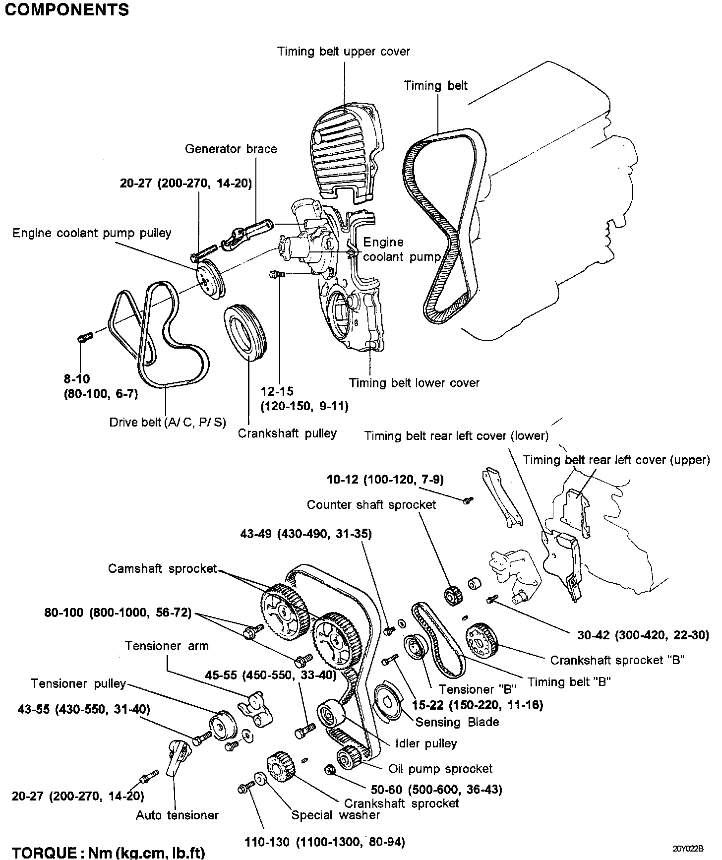
REMOVAL
1. Remove the crankshaft pulley, engine coolant pump pulley and drive belt.
2. Remove the timing belt cover.
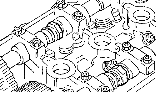
3. Turn the crankshaft clockwise and align the timing marks so as to bring the No.1 cylinder to compression top-dead-center position. At this time the timing marks of the camshaft sprocket and the upper surface of the rocker cover should coincide, and the dowel pin of the camshaft sprocket should be at the upper side. Remove the auto tensioner.
CAUTION: Rotate the crankshaft clockwise.
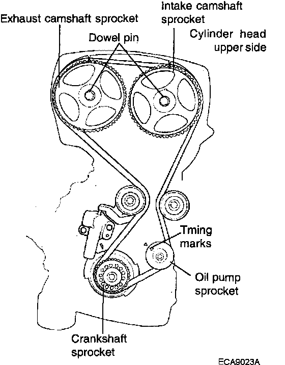
4. Remove the timing belt.
NOTE: If the timing belt is reused, make an arrow mark indicating the turning direction (or the front of the engine) to make sure that the belt is reinstalled in the same direction as before.
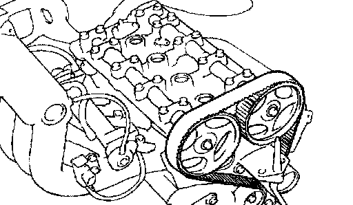
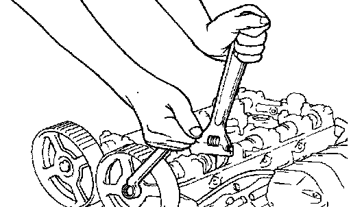
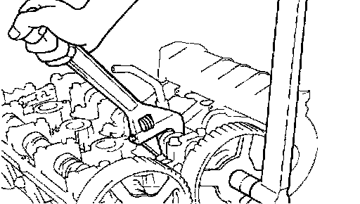
5. Remove the camshaft sprockets.
NOTE: Be careful not to damage the cylinder head with the wrench.
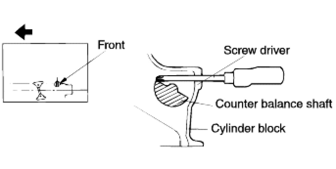
6. When the oil pump sprocket nut is removed, first remove the plug at left side of the cylinder block and insert a screwdriver to check the left counter balance shaft in position. Screwdriver used for this purpose should have a shaft 8 mm (0.3 inch) in diameter which can be inserted more than 60 mm (2.36 inch)

7. Remove the oil pump sprocket retaining nut and remove the oil pump sprocket.
8. Loosen the right counter balance shaft sprocket mounting bolt until it can be loosened by hand.
9. Next, remove tensioner "B" and remove timing belt "B".
CAUTION: After timing belt "B" has been removed, do not attempt to loosen bolt while holding sprocket with pliers, etc.
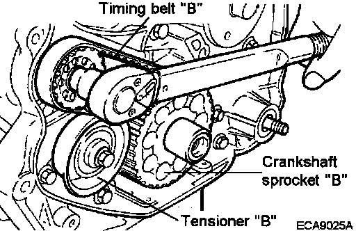
10. Remove the crankshaft sprocket "B" from crankshaft.
INSPECTION
Sprockets, Tensioner Pulley, and Idler Pulley
1. Check the camshaft sprocket, crankshaft sprocket, tensioner pulley, and idler pulley for abnormal wear, cracks, or damage. Replace as necessary.
2. Inspect the tensioner pulley and the idler pulley for easy and smooth pulley rotation and check for play or noise. Replace as necessary.
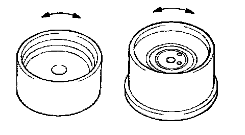
3. Replace if there is grease leak.
Auto Tensioner
1. Check the auto tensioner for leak and replace as necessary.
2. Check the rod end for wear or damage and replace as necessary.
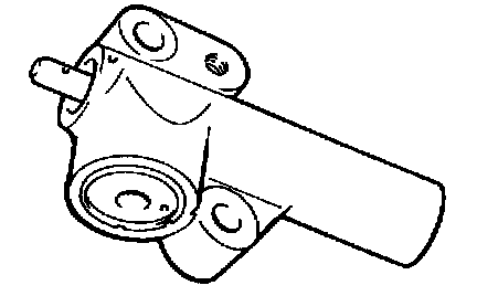
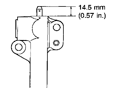
3. Measure the rod protrusion. If it is out of specification, replace the auto tensioner.
Standard value 14.5 mm (0.57 inch)
4. Using a vise softjaws push the auto tensioner rod. If the rod can be easily retracted, replace the auto tensioner. You should feel a great deal of resistance when pushing the rod in.
CAUTION: Clamp the auto tensioner in the vise so that it can be level. Use soft jaws in the vise to avoid damaging the auto tensioner.
Timing Belt
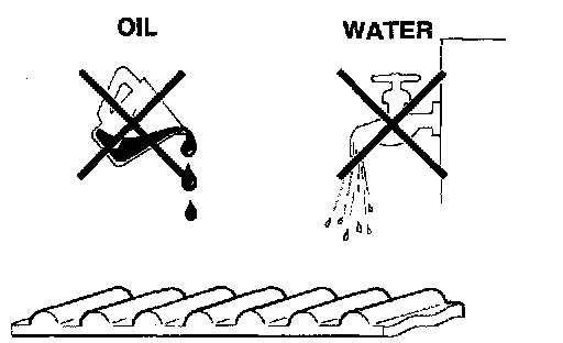
1. Check the belt for oil or dust deposits. Replace if necessary. Small deposits should be wiped away with a dry cloth or paper. Do not clean with solvent.
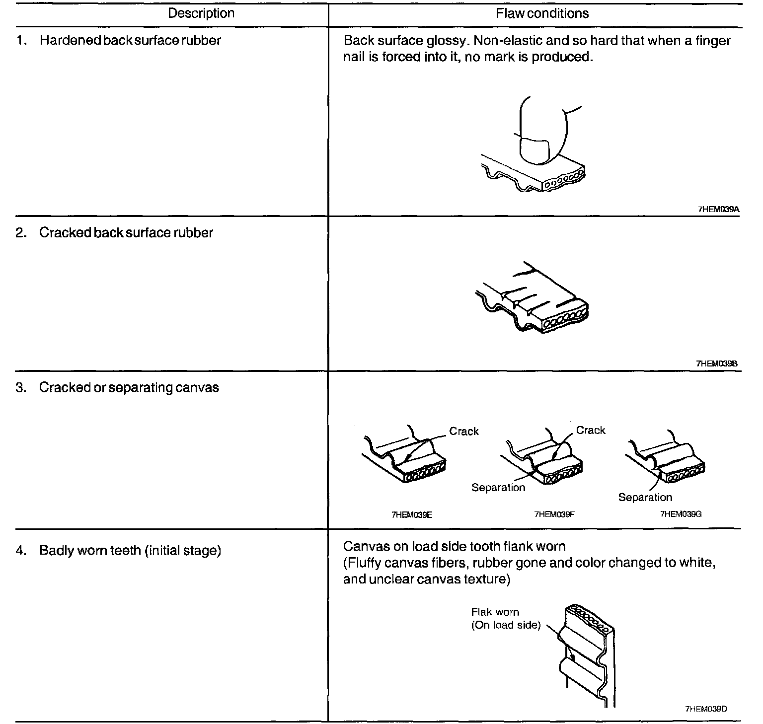
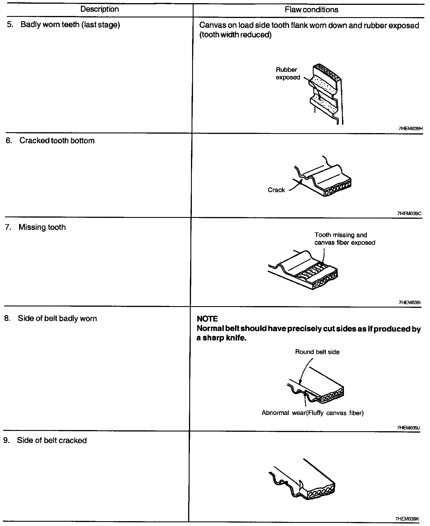
2. When the engine is overhauled or belt tension adjusted, check the belt in detail. If the flaws are evident, replace the belt with a new one.
INSTALLATION
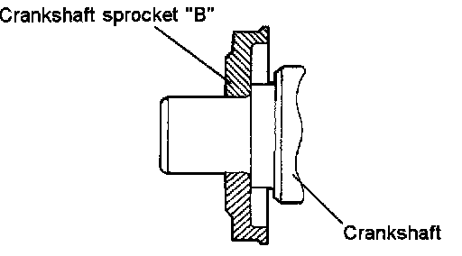
1. Install crankshaft sprocket "B" into crankshaft.
CAUTION: Pay special attention to the direction of the flange. If it is installed in the wrong direction, a broken belt could result from it.
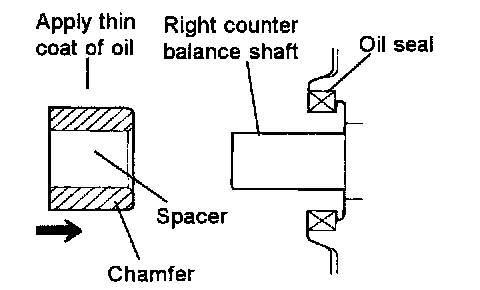
2. Lightly apply engine oil to the outer surface of spacer, and then install the spacer to the right counter balance shaft. Be sure to install as the direction shown in illustration.
3. Install the counter balance shaft sprocket onto the right counter balance shaft, and then tighten flange bolt by hand tightly.
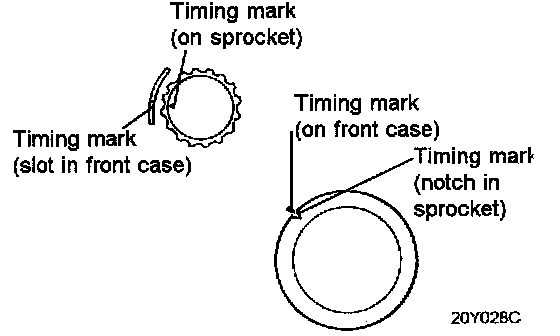
4. Align the timing mark on each sprocket with the corresponding timing mark on the front case.
5. When the timing belt "B" is installed, make certain that tension side has no slack. Install tensioner "B" in the center of pulley located on the left side of mounting bolt.
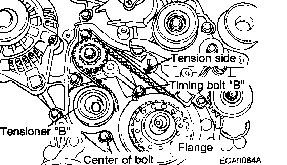
6. Lift tensioner "B" to tighten the timing belt "B" so that its tension side will be pulled tight. In this condition, tighten a bolt to secure tensioner "B". When a bolt is tightened, be careful to prevent from turning together. If the shaft is turned together, the belt will be overtightened.
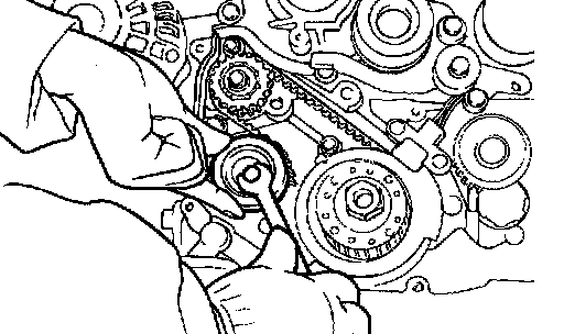
7. Check to ensure that timing marks are in alignment.
8. Check to ensure that when the center of span on the tension side is depressed with index finger in direction of arrow, deflection of belt is within specification.
Belt deflection 5 - 7 mm (0.2 - 0.3 inch)

9. Install the flange and crankshaft sprocket onto crankshaft. Be sure to install as the direction shown in illustration.
CAUTION: Pay attention to direction of flange. If it is installed in wrong direction, a broken belt could result.
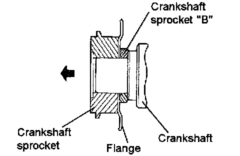
10. Install the special washer and sprocket bolt to crankshaft, and then tighten the sprocket bolt.
Tightening torque Crankshaft sprocket bolt 110 - 130 Nm (1100 - 1300 kg.cm, 80 - 94 ft. lbs.)
11. Insert a screwdriver through the plug hole in left side of cylinder block to keep shaft in position.
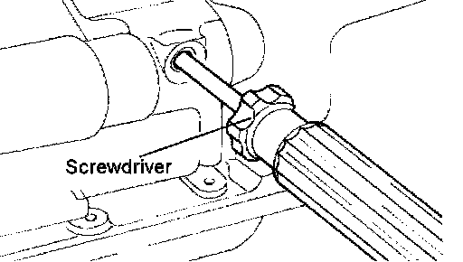
12. Install the oil pump sprocket, and tighten the nut to the specified torque.
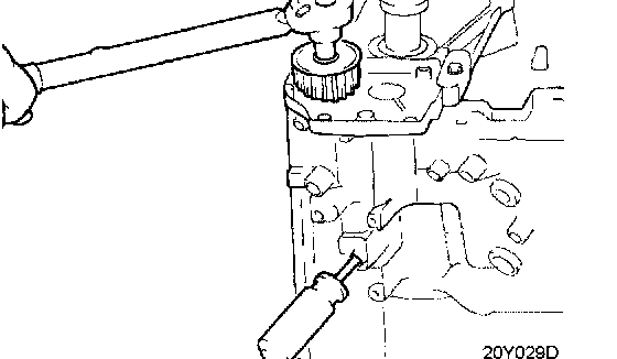
13. Install the camshaft sprocket and tighten the bolt to the specified torque.
Tightening torque Camshaft sprocket bolt 80 - 100 Nm (800 - 1000 kg.cm, 56 - 72 ft. lbs.)
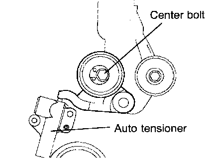
14. Install the auto tensioner.
CAUTION: Leave the set pin installed in the auto tensioner
Tightening torque Auto tensioner bolt 19.6 - 26.5 Nm (2.0 - 2.7 kg.cm, 14.5 - 19.5 ft. lbs.)
NOTE:
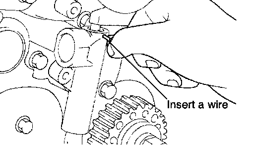
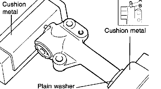
If the auto tensioner rod is in its fully extended position, reset it as follows.
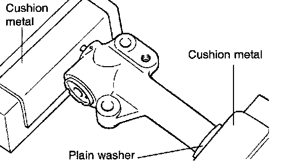
^ Clamp it in the vise with soft jaws in a level position. Apply a plain washer if there is a plug at the bottom of the auto tensioner.
^ Push in the rod slowly with the vise until the set hole A in the rod is aligned with the set hole B in the cylinder.
^ Insert a wire to the set hole A and B.
15. Install the tensioner pulley onto the tensioner arm.
CAUTION: Leave the wire installed in the auto tensioner.
16. Align the timing marks of the camshaft sprocket to the timing marks of the rocker cover. The dowel pin of the camshaft sprocket should be at the upper side.
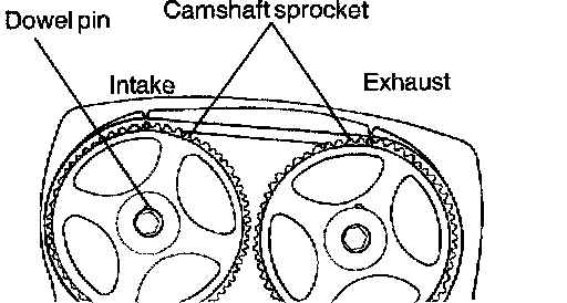
NOTE:
^ The identification mark is on the camshaft sprocket.
^ Before installing the timing belt, If the timing mark of cam sprocket doesn't coincide with that of rocker cover, do not rotate the cam sprocket more than 2 teeth of sprocket in any direction.
^ Rotating sprocket more than 2 teeth makes valve and piston touched each other.
^ In case of rotating the cam sprocket unavoidably more than 2 teeth, rotate the cam sprocket after rotating crank sprocket counter clockwise on basis of timing mark.
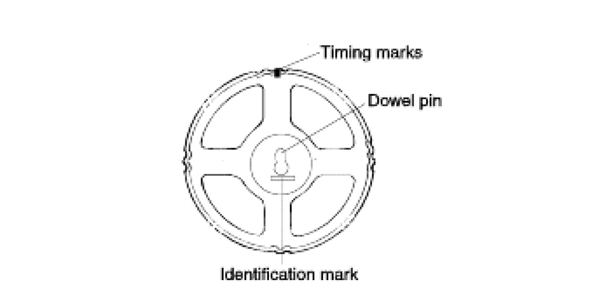
17. Align the timing marks of each sprocket and install the timing belt in this order. Crankshaft sprocket-Oil pump sprocket-Idler pulley-Exhaust camshaft sprocket-Intake camshaft sprocket-Tensioner pulley.
NOTE:
^ In this step, No.1 is in TDC (Compression Stroke).
^ When the timing mark of oil pump sprocket is aligned, first remove the plug at the left side of the cylinder block and insert a screwdriver to check the left counter balance shaft in position.
Screwdriver used for this purpose should have a shaft 8mm (0.3in) in diameter which can be inserted more than 60mm (2.36in).
^ Install the plug at left side of the cylinder block after checking timing.
18. Remove a wire from the auto tensioner.
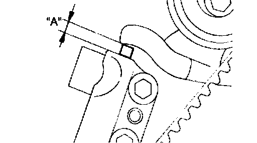
Rotate the crankshaft two complete turns clockwise and leave it for about 5 minutes. Then, measure the auto tensioner protrusion "A" (distance between the tensioner arm and auto tensioner body) to ensure that it is up to specification. If the protrusion exceeds specification, repeat step 14-18
Standard value 5.5 - 9.0 mm (0.22 - 0.35 inch)
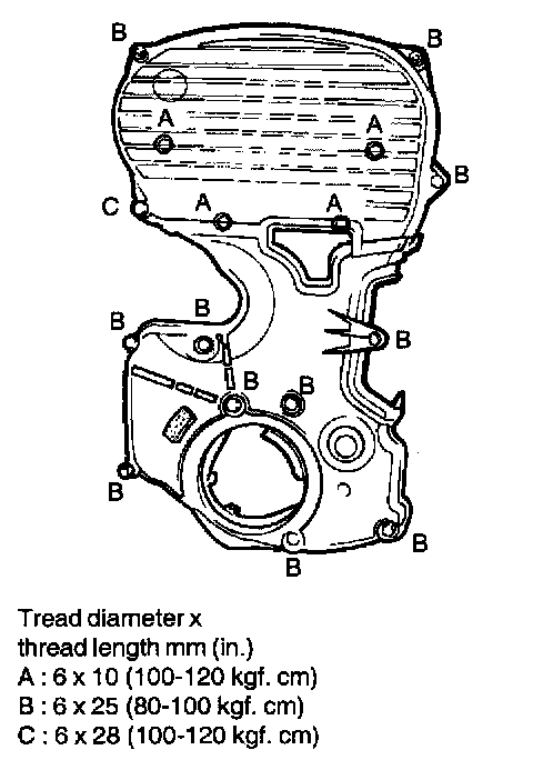
19. Install the timing belt lower cover and the timing belt upper cover.
Factory Service Tools
Use the Manual With the Right Hardware
Pair factory procedures with proven DIY tools so the instructions are easier to execute.
Disclosure: Verified tool recommendations may earn an affiliate commission at no cost to you.
When to See a Mechanic
Stop DIY work and contact a certified mechanic immediately if any of the following apply:
- • You smell fuel, burning insulation, or see smoke.
- • Brakes feel soft, pull hard to one side, or make grinding noises.
- • The engine overheats, stalls repeatedly, or misfires under load.
- • You are missing required tools, torque specs, or safe lifting equipment.
- • You are not confident in the next step or safety outcome.