
Safety Warning
DIY auto repair can cause serious injury, fire, or vehicle damage. These guides are for informational purposes only. Always follow OEM torque specs, wear PPE, and consult a certified mechanic if you are unsure. You are solely responsible for your safety.
2012 Jeep Compass 2WD L4-2.4LFACTORY OEM SERVICE PROCEDURE
Back Window Motor: Testing and Inspection
DIAGNOSIS AND TESTING - REAR WINDOW MOTOR INOPERATIVE
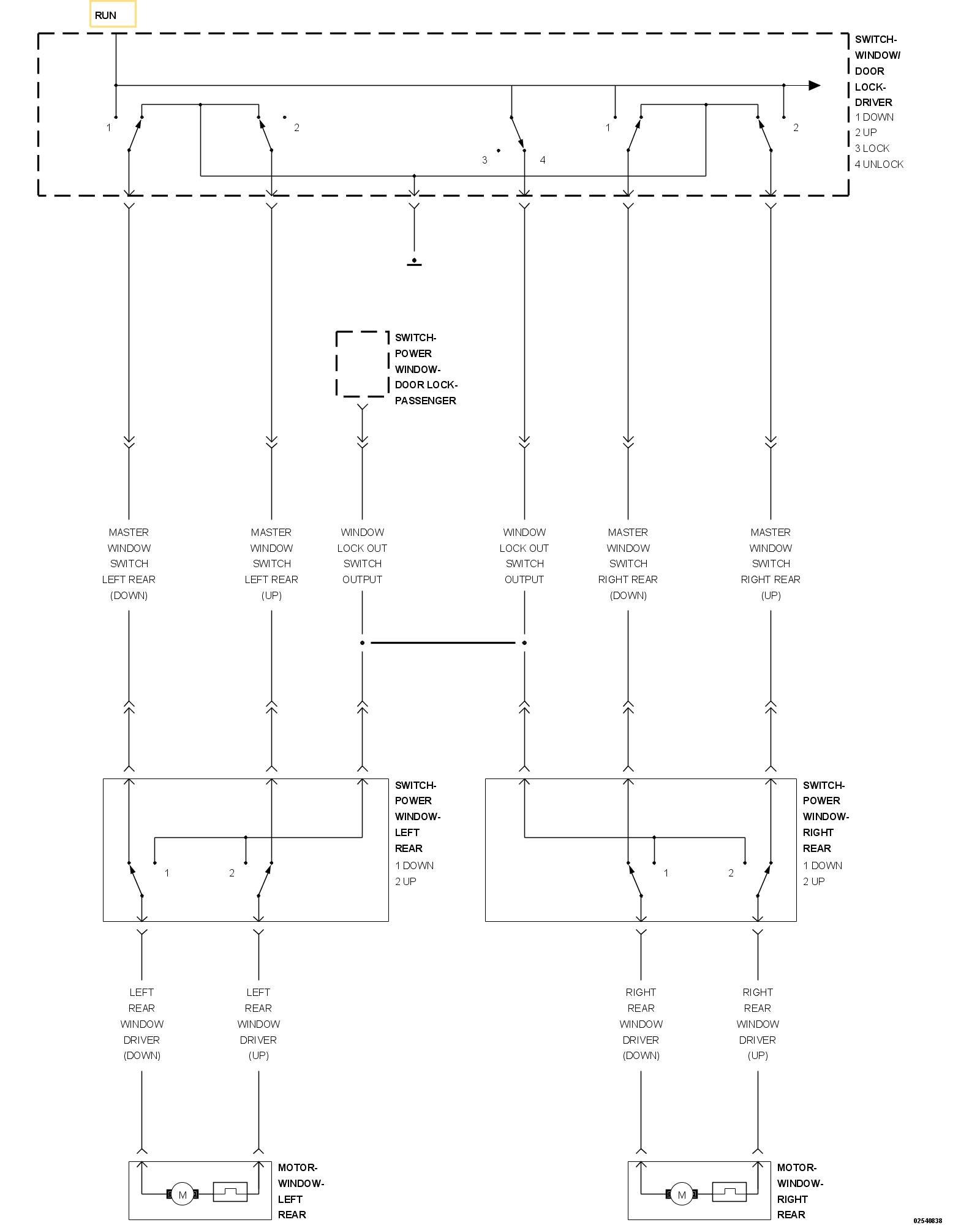
For a complete wiring diagram, refer to the Wiring Information.
NOTE: The graphics in this test show the Left Rear connectors, the Right side connectors are similar, refer to the Wiring Information for the connector pinouts.
Theory of Operation
By studying the schematic above, you will notice that the window driver circuits both go to ground when the switches are in the neutral position. In the driver switch, when a switch is moved to lower or raise a window, the switch leaves the ground contact, and supplies 12 volts to the Master Window Switch Rear Up or Down circuit. Likewise in the rear switch, when a switch is moved it leaves the ground contact and supplies 12 volts (through the window lockout switch output circuit) to the Rear Window Driver Up or Down circuit.
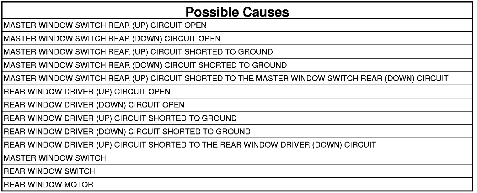
1. TEST FOR DIAGNOSTIC TROUBLE CODES
1. Turn the ignition on.
2. With the scan tool, read the DTCs.
Does the scan tool display any Power Window related DTCs?
Yes
- Testing and Inspection Perform the appropriate diagnostic procedure.
No
- Go To 2
2. CHECK FOR OPEN OR SHORTED TOGETHER CIRCUIT
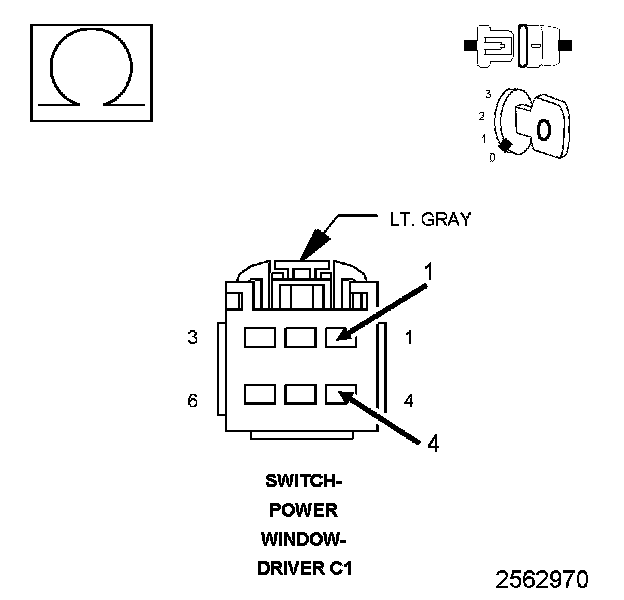
1. Turn the ignition off.
2. Disconnect the Driver Window Switch C1 connector.
3. Measure the resistance between the Master Window Switch Left Rear (Up) circuit and the Master Window Switch Left Rear (Down) circuit in the Driver Switch C1 connector.
Select the appropriate reading.
Below.05 of an Ohm
- Go To 11
Between 0.6 and 15.5 Ohms
- Go To 3
Above 15.6 Ohms
- Go To 5
3. CHECK FOR SHORTED CIRCUIT
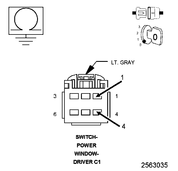
1. Measure the resistance between ground and the Master Window Switch Left Rear (Up) circuit in the Driver Switch C1 connector.
2. Measure the resistance between ground and the Master Window Switch Left Rear (Down) circuit in the Driver Switch C1 connector.
Is the resistance below 20k Ohms on either or both circuits?
Yes
- Go To 14
No
- Go To 4
4. DRIVER WINDOW SWITCH OR MOTOR
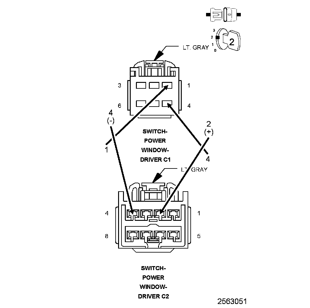
1. Disconnect the Driver Window Switch C2 connector.
2. Turn the ignition on.
3. Connect a Jumper wire between the Ignition Switch Output circuit (cavity 2 in the Driver Switch C2 connector) and the Master Window Switch Left Rear (Down) circuit (Cavity 4 in the Driver Switch C1 connector).
4. Connect a Jumper wire between the Master Window Switch Left Rear (Up) circuit (Cavity 1 in the Driver Switch C1 connector) and momentarily touch it to the Ground circuit (cavity 4 in the Driver Switch C2 connector). Reverse the wires at the C1 connector if there is a short to ground.
NOTE: For the Right Rear Motor, substitute cavities 2 and 3 for cavities 1 and 4.
5. If the motor ran in one direction, reverse the jumper wires (in the C1 connector) to run the motor in the opposite direction.
Did the window motor operate properly in both directions?
Yes
- Replace the Driver Window Switch.
- Perform the BODY VERIFICATION TEST. Body Verification Test.
No
- Replace the Window Motor (regulator).
- Perform the BODY VERIFICATION TEST. Body Verification Test.
5. OPEN WINDOW (UP) CIRCUIT

1. Disconnect the Left Rear Window Motor connector.
2. Measure the resistance between the Master Window Switch Left Rear (Up) circuit in the Driver Window Switch C1 connector and the Left Rear Window Driver (Up) circuit in the Left Rear Window Motor connector.
Is the resistance below 3.0 Ohms?
Yes
- Go To 8
No
- Go To 6
6. OPEN MASTER WINDOW SWITCH LEFT REAR (UP) CIRCUIT
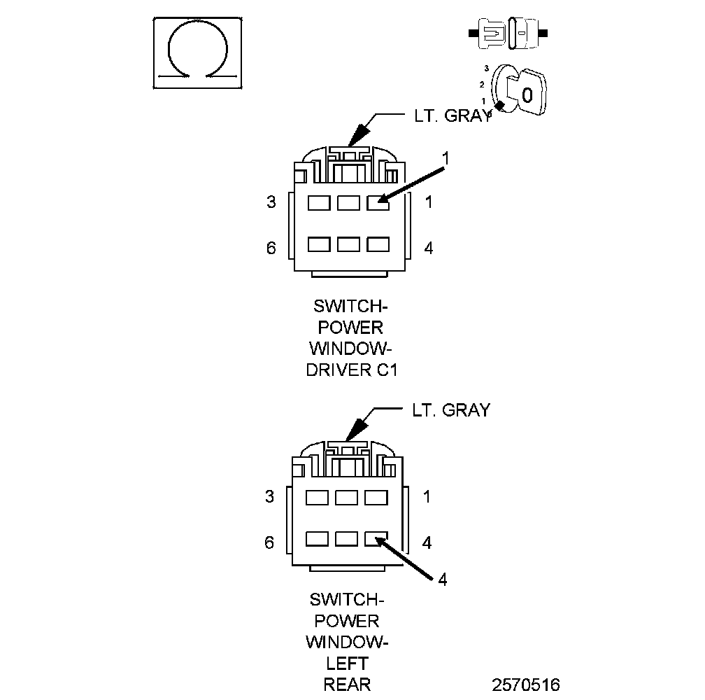
1. Disconnect the Left Rear Window Switch connector.
2. Measure the resistance of the Master Window Switch Left Rear (Up) circuit between the Driver Window Switch C1 connector and the Left Rear Window Switch connector.
Is the resistance below 3.0 Ohms?
Yes
- Go To 7
No
- Repair the open in the Master Window Switch Left Rear (Up) circuit.
- Perform the BODY VERIFICATION TEST. Body Verification Test.
7. OPEN LEFT REAR WINDOW DRIVER (UP) CIRCUIT
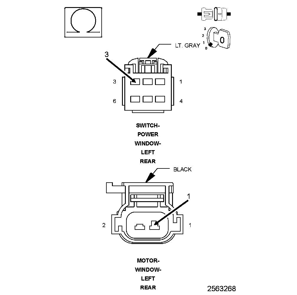
1. Measure the resistance of the Left Rear Window Driver (Up) circuit between the Left Rear Window Switch connector and the Left Rear Window Motor connector.
Is the resistance below 3.0 Ohms?
Yes
- Replace the Left Rear Window Switch.
- Perform the BODY VERIFICATION TEST. Body Verification Test.
No
- Repair the open in the Left Rear Window Driver (Up) circuit.
- Perform the BODY VERIFICATION TEST. Body Verification Test.
8. OPEN WINDOW (DOWN) CIRCUIT
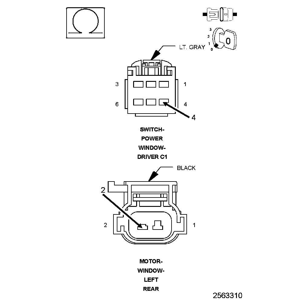
1. Measure the resistance between the Master Window Switch Left Rear (Down) circuit in the Driver Window Switch C1 connector and the Left Rear Window Driver (Down) circuit in the Left Rear Window Motor connector.
Is the resistance below 3.0 Ohms?
Yes
- Replace the Left Rear Window Motor.
- Perform the BODY VERIFICATION TEST. Body Verification Test.
No
- Go To 9
9. OPEN MASTER WINDOW SWITCH LEFT REAR (DOWN) CIRCUIT
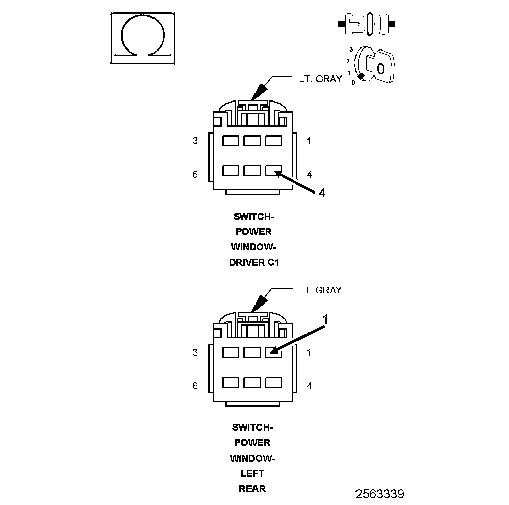
1. Disconnect the Left Rear Window Switch connector.
2. Measure the resistance of the Master Window Switch Left Rear (Down) circuit between the Driver Window Switch C1 connector and the Left Rear Window Switch connector.
Is the resistance below 3.0 Ohms?
Yes
- Go To 10
No
- Repair the open in the Master Window Switch Left Rear (Down) circuit.
- Perform the BODY VERIFICATION TEST. Body Verification Test.
10. OPEN LEFT REAR WINDOW DRIVER (DOWN) CIRCUIT
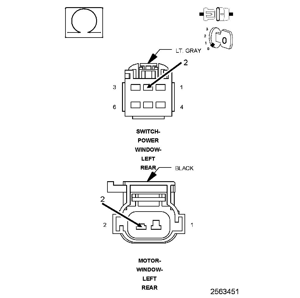
1. Measure the resistance of the Left Rear Window Driver (Down) circuit between the Left Rear Window Switch connector and the Left Rear Window Motor connector.
Is the resistance below 3.0 Ohms?
Yes
- Replace the Left Rear Window Switch.
- Perform the BODY VERIFICATION TEST. Body Verification Test.
No
- Repair the open in the Left Rear Window Driver (Down) circuit.
- Perform the BODY VERIFICATION TEST. Body Verification Test.
11. SHORTED REAR MOTOR
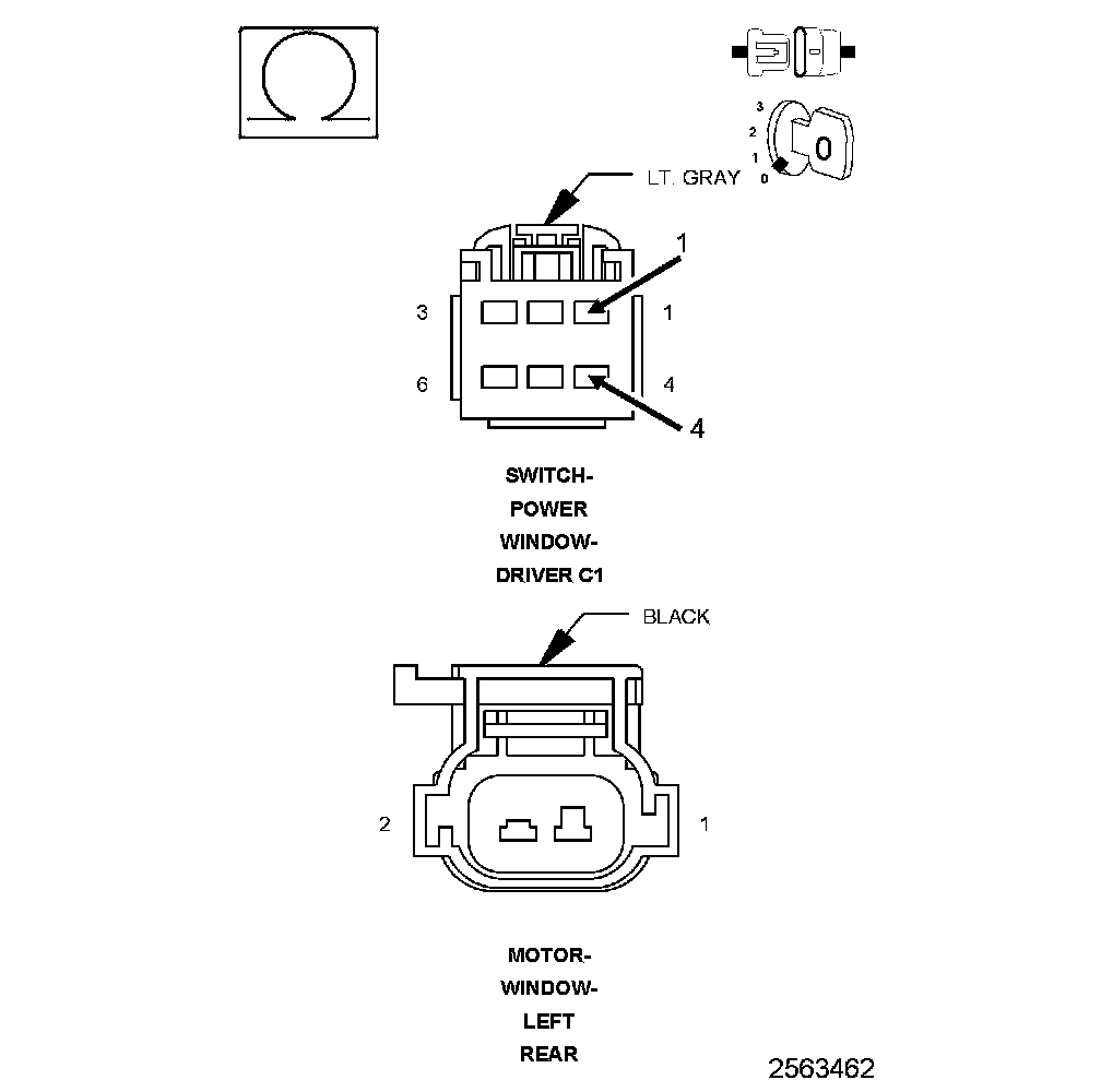
NOTE: The graphics show the Left Rear Motor circuit, the Right Rear uses Cavities 2 and 3.
1. Disconnect the Rear Window Motor connector.
2. Measure the resistance between the Master Window Switch Left Rear (Up) circuit and the Master Window Switch Left Rear (Down) circuit in the Driver Window Switch C1 connector.
Is the resistance below 20k Ohms?
Yes
- Go To 12
No
- Replace the Rear Window Motor.
- Perform the BODY VERIFICATION TEST. Body Verification Test.
12. MASTER WINDOW SWITCH LEFT REAR (UP) CIRCUIT SHORTED TO THE MASTER WINDOW SWITCH LEFT REAR (DOWN) CIRCUIT
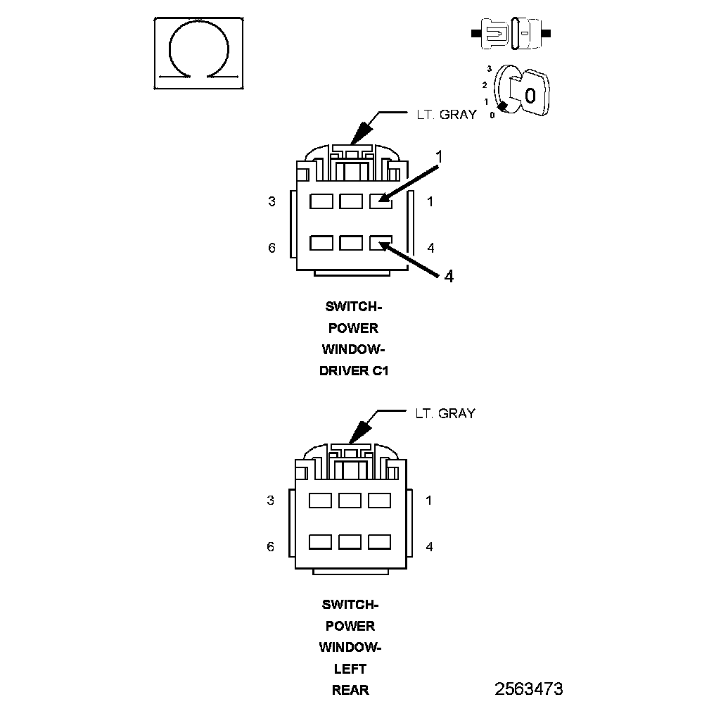
1. Disconnect the Left Rear Window Switch connector.
2. Measure the resistance between the Master Window Switch Left Rear (Up) circuit and the Master Window Switch Left Rear (Down) circuit in the Driver Window Switch C1 connector.
Is the resistance below 20k Ohms?
Yes
- Repair the short between the Master Window Switch Left Rear (Up) circuit and the Master Window Switch Left Rear (Down) circuit.
- Perform the BODY VERIFICATION TEST. Body Verification Test.
No
- Go To 13
13. REAR WINDOW DRIVER (UP) CIRCUIT SHORTED TO THE REAR WINDOW DRIVER (DOWN) CIRCUIT
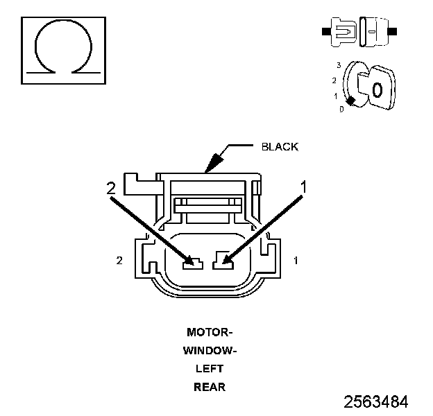
1. Measure the resistance between the Left Rear Window Driver (Up) circuit and the Left Rear Window Driver (Down) circuit in the Left Rear Window Motor connector.
Is the resistance below 20k Ohms?
Yes
- Repair the short between the Left Rear Window Driver (Up) circuit and the Left Rear Window Driver (Down) circuit.
- Perform the BODY VERIFICATION TEST. Body Verification Test.
No
- Replace the Rear Window Switch.
- Perform the BODY VERIFICATION TEST. Body Verification Test.
14. CHECK FOR SHORTED MOTOR
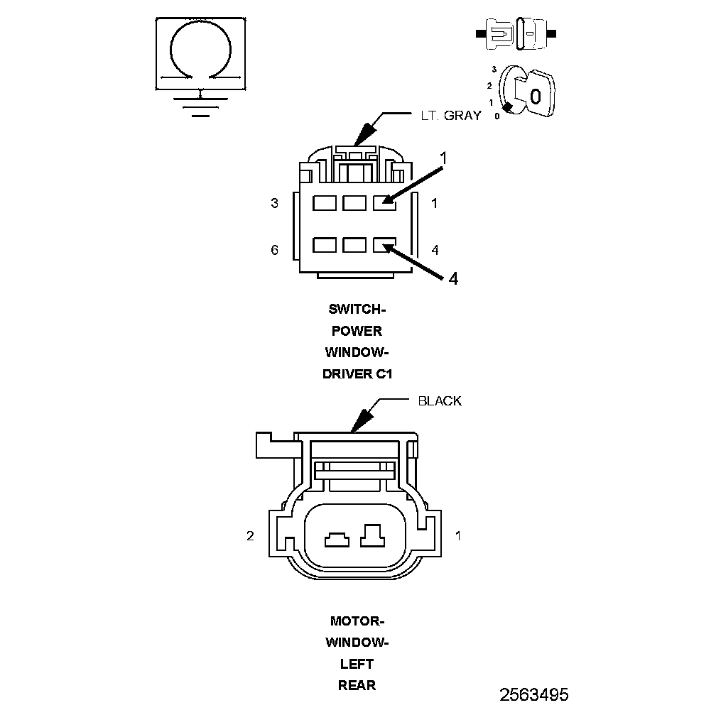
1. Disconnect the Left Rear Window Motor connector.
2. Measure the resistance between ground and the Master Window Switch Left Rear (Up) circuit in the Driver Switch C1 connector.
3. Measure the resistance between ground and the Master Window Switch Left Rear (Down) circuit in the Driver Switch C1 connector.
Is the resistance below 20k Ohms on either or both circuits?
Yes
- Go To 15
No
- Replace the Window Motor (regulator).
- Perform the BODY VERIFICATION TEST. Body Verification Test.
15. CHECK FOR SHORT TO GROUND
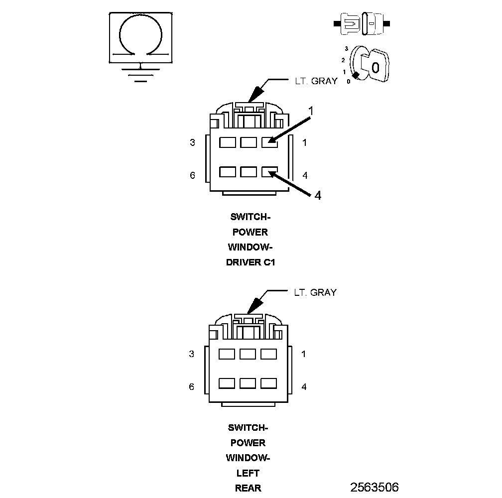
1. Disconnect the Left Rear Window Switch connector.
2. Measure the resistance between ground and the Master Window Switch Left Rear (Up) circuit in the Driver Switch C1 connector.
3. Measure the resistance between ground and the Master Window Switch Left Rear (Down) circuit in the Driver Switch C1 connector.
Is the resistance below 20k Ohms on either or both circuits?
Yes
- Repair the short to ground in the Master Window Switch Left Rear (Up) or (Down) circuit.
- Perform the BODY VERIFICATION TEST. Body Verification Test.
No
- Repair the short to ground in the Left Rear Window Driver (Up) or (Down) circuit between the Motor and the Rear Window Switch.
- Perform the BODY VERIFICATION TEST. Body Verification Test.
Factory Service Tools
Use the Manual With the Right Hardware
Pair factory procedures with proven DIY tools so the instructions are easier to execute.
Disclosure: Verified tool recommendations may earn an affiliate commission at no cost to you.
When to See a Mechanic
Stop DIY work and contact a certified mechanic immediately if any of the following apply:
- • You smell fuel, burning insulation, or see smoke.
- • Brakes feel soft, pull hard to one side, or make grinding noises.
- • The engine overheats, stalls repeatedly, or misfires under load.
- • You are missing required tools, torque specs, or safe lifting equipment.
- • You are not confident in the next step or safety outcome.