
Safety Warning
DIY auto repair can cause serious injury, fire, or vehicle damage. These guides are for informational purposes only. Always follow OEM torque specs, wear PPE, and consult a certified mechanic if you are unsure. You are solely responsible for your safety.
2009 Jeep Commander 4WD V8-5.7LFACTORY OEM SERVICE PROCEDURE
Instrument Panel - Installation
INSTALLATION
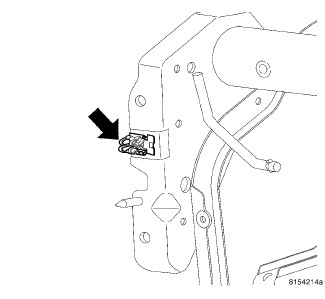
1. Before proceeding with installation of the instrument panel assembly, remove the load clips from each a-pillar and install onto the sides of the panel using the screw.
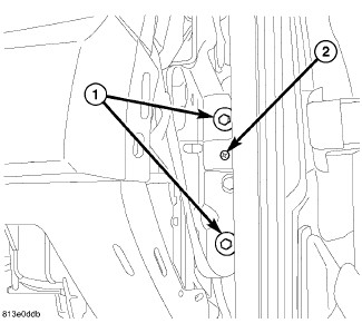
2. Place the instrument panel into the vehicle and position onto the a-pillars using the load clips (2).
3. Install the two bolts on the right side and tighten the bolts to 11 Nm (95 in. lbs.).
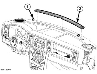
4. Install the two fenceline nuts (1) and install the defroster grille (2).
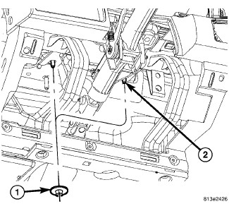
5. Guide the peddle support studs (2) on the drivers side, into the slots in the instrument panel reinforcement.
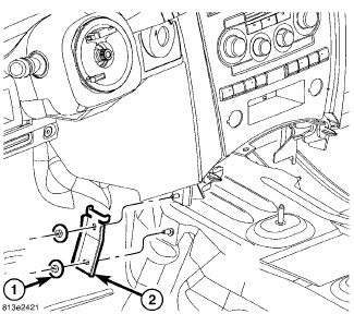
6. Position the center stack brackets (2) in front of the duct work.
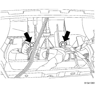
7. Continue to rotate the instrument panel back and guide the tube brackets located in the radio opening, into the HVAC.
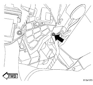
8. Install the screw at the bottom of the column opening next to the center stack up from the bottom attaching the HVAC.
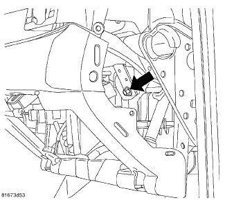
9. Install the bolt at the HVAC blower motor housing.
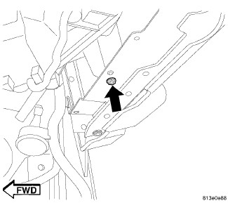
10. Install the screw at the bottom of the glove box opening to the blower motor housing support.
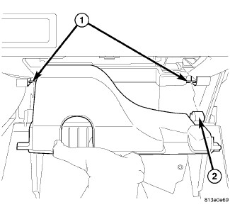
11. Snap the lower glove box hinges (2) over the pivots (1) and rotate up.
12. Push the stop tabs down and close the glove box.
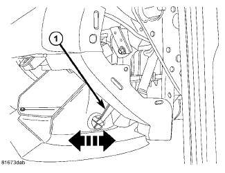
13. Connect the stabilizer to the outer side of the box compartment.
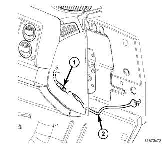
14. Connect the radio antenna cable (1 and 2).
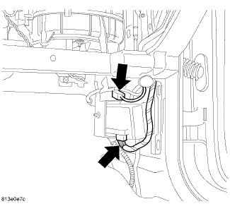
15. Connect the right side wiring.
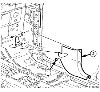
16. Install the right hush panel trim.
17. Install the right cowl trim and position the door seal back.
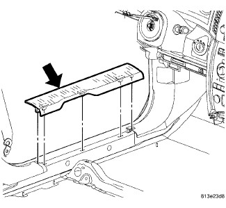
18. Position the right side door sill trim and seat fully.* Left side shown, right side similar.
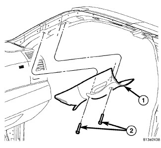
19. Install the right a-pillar trim, the bolts and position the door seal back.
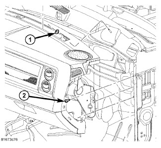
20. Install the two bolts on the left side and tighten to 11 Nm (95 in. lbs.).* Right side shown, left side similar.
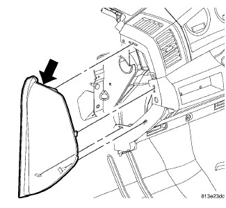
21. Position the right side end cap and seat fully.* Left side shown, right side similar.
22. Install the two nuts (1) on the studs (2) above the column tighten the nuts to 12 Nm (105 in. lbs.).
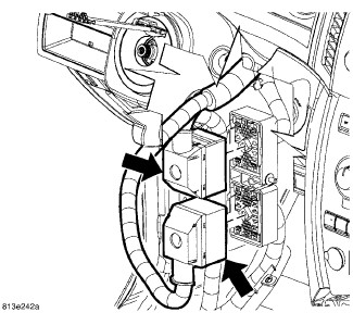
23. Connect the two left bulk connectors.
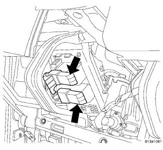
24. Connect the two fuse block connectors.
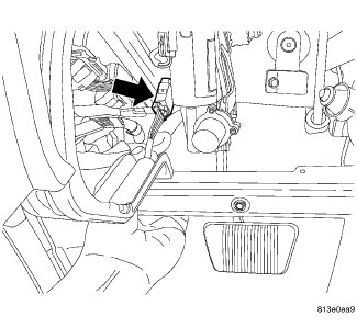
25. Connect the white connector to adjustable brake pedal.
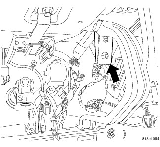
26. Install the grounds within the steering column opening and install the bolts.
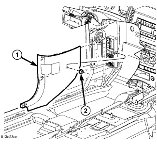
27. Install the left cowl trim panel (1) and install the nut (2).
28. Install the left door sill.
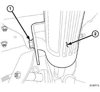
CAUTION: Do not turn the steering wheel more than 90° or damage to the clockspring may occur.
29. Install the column cross bolt (1) and tighten to 12 Nm (105 in. lbs.).
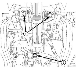
30. Position the steering column shaft into the slip joint.
31. Lift the column into position and install the bolts (1).
32. Tighten the bolts to 12 Nm (105 in. lbs.).
33. Slide the coupler onto the column shaft and install a new coupler bolt (2). Tighten the coupler bolt to 49 Nm (36 ft. lbs.).
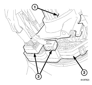
34. Connect the electrical connector (3) for the multi-function switch (2).
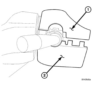
35. Install the upper shroud (1) on the column.
36. Install the lower shroud (2) to the column.
37. Snap the two halves back into place.
38. Install the three mounting bolts to secure the shroud in place.
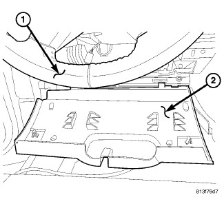
39. Snap the steering column opening cover (2) lower hinges onto the pins and roll cover up.
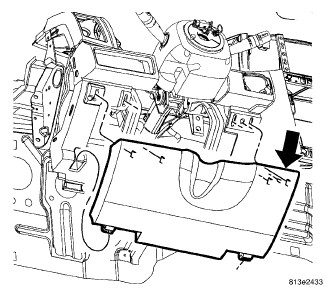
40. Seat the upper retaining clips fully.
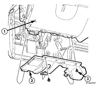
41. Install the hush panel.
42. Connect the column electrical connectors.
43. Install the column covers.
44. Install the left a-pillar trim, the bolts and position the door seal back.* Right a-pillar trim shown, left similar.
45. Position the left side end cap and seat fully.
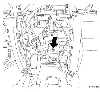
46. Install the center support nut onto the stud.
47. Install the two HVAC bolts within the radio opening.
48. Install the radio.
49. Install the radio bezel.
50. Install the left and right center support brackets and nuts and tighten to 12 Nm (105 in. lbs.).* Left side shown, right side similar.
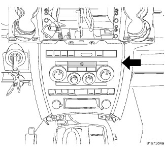
51. Position the center wire harness and connect the electrical connectors.
52. Install the center bezel.
53. Install the screw inside the lower storage bin, if equipped.
54. Position the defroster vents (2) and seat fully.
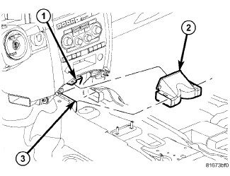
55. Install HVAC floor duct (2).
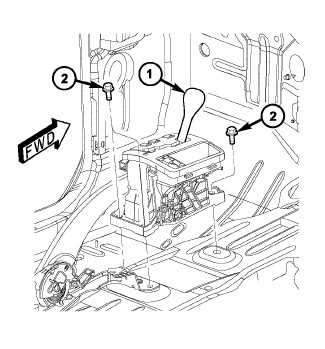
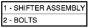
56. Install the shifter mechanism (1). Transmission Shifter - Installation
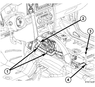
57. Position the wire harness (2) back, install the harness hangers (1) and install the ground (4) and screw (3).
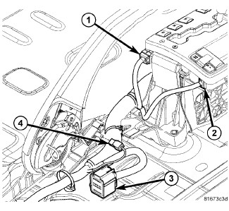
58. Connect the center harness electrical connectors (ground, module, shifter, brake lever).

59. Install the center floor duct (3).
60. Position the console (1) into the vehicle and install the screws (2).
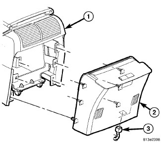
61. Connect the electrical connector (3) and install the rear cover (2) onto the console (1).
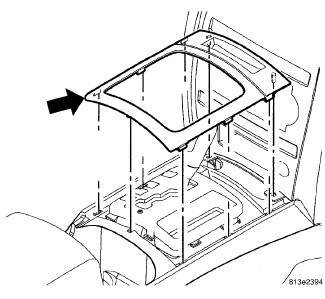
62. Position the shifter bezel and seat fully.
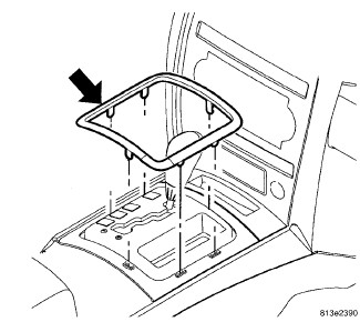
63. Position the shifter bezel trim ring and seat fully.
Factory Service Tools
Use the Manual With the Right Hardware
Pair factory procedures with proven DIY tools so the instructions are easier to execute.
Disclosure: Verified tool recommendations may earn an affiliate commission at no cost to you.
When to See a Mechanic
Stop DIY work and contact a certified mechanic immediately if any of the following apply:
- • You smell fuel, burning insulation, or see smoke.
- • Brakes feel soft, pull hard to one side, or make grinding noises.
- • The engine overheats, stalls repeatedly, or misfires under load.
- • You are missing required tools, torque specs, or safe lifting equipment.
- • You are not confident in the next step or safety outcome.
Rather have a pro handle this?
A certified mobile mechanic comes to your home or office. They bring the tools, you stay comfortable. No tow truck, no waiting room, no surprises.
Comes to youSame-day available12-month warranty
Get a Free QuoteNo obligation. See pricing before you book.