
Safety Warning
DIY auto repair can cause serious injury, fire, or vehicle damage. These guides are for informational purposes only. Always follow OEM torque specs, wear PPE, and consult a certified mechanic if you are unsure. You are solely responsible for your safety.
2008 Jeep Commander 4WD V8-4.7LFACTORY OEM SERVICE PROCEDURE
System Specifications
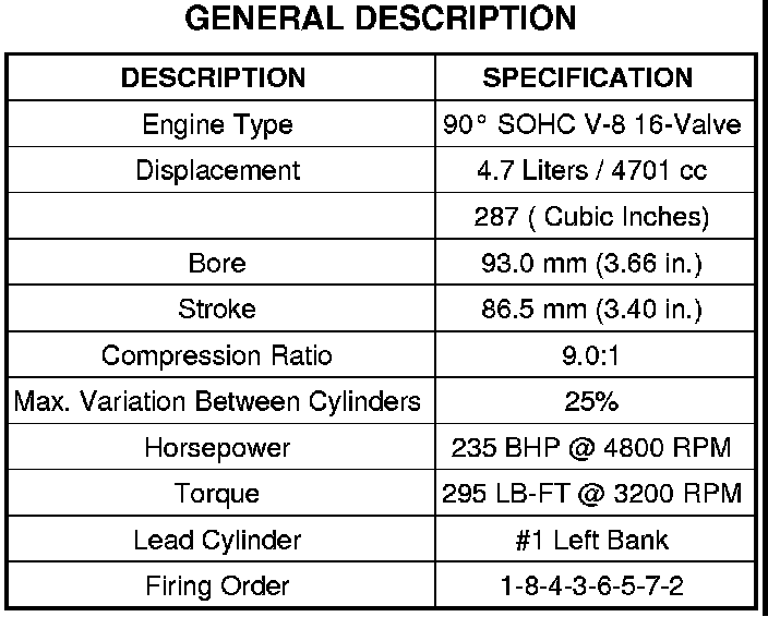
GENERAL DESCRIPTION
General Description:
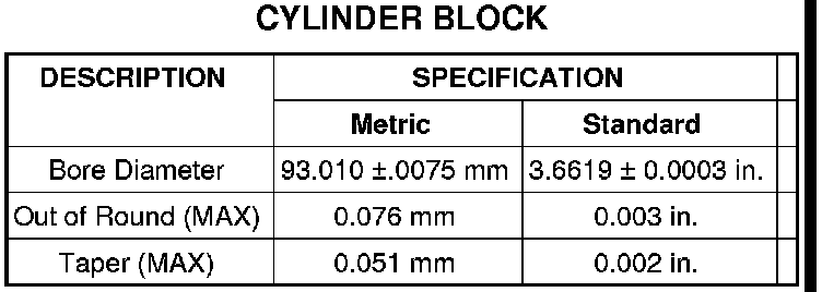
CYLINDER BLOCK
Cylinder Block:
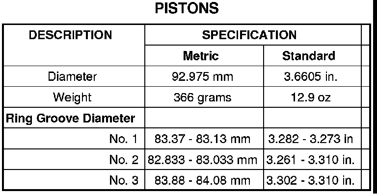
PISTON
Pistons:
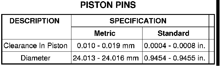
PISTON PINS
Piston Pins:
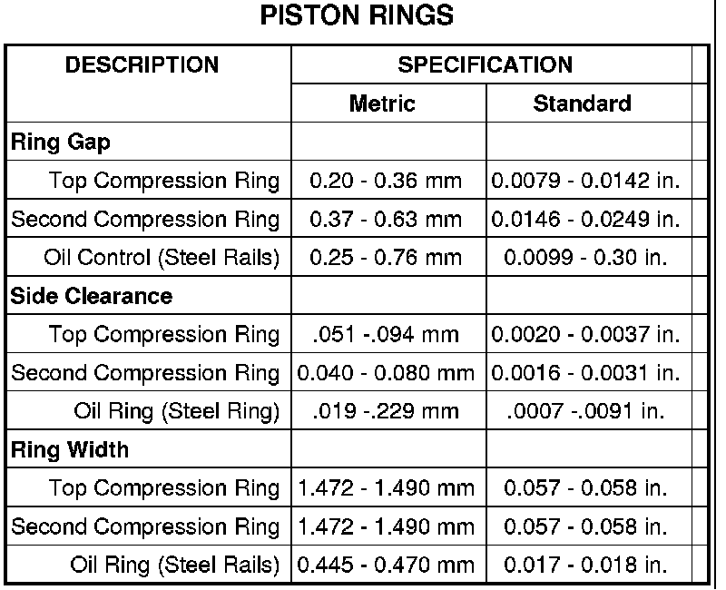
PISTON RINGS
Piston Rings:
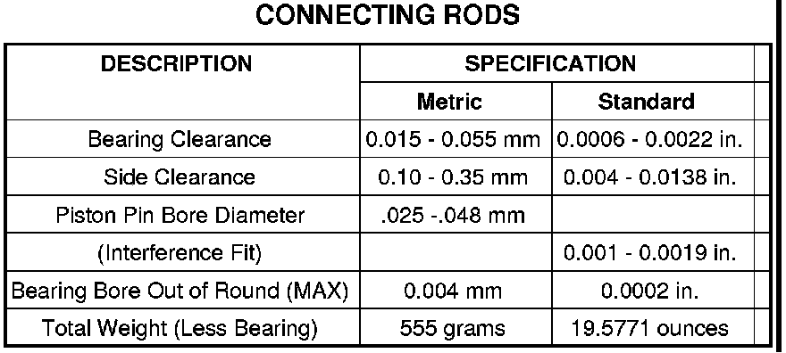
CONNECTING RODS
Connecting Rods:
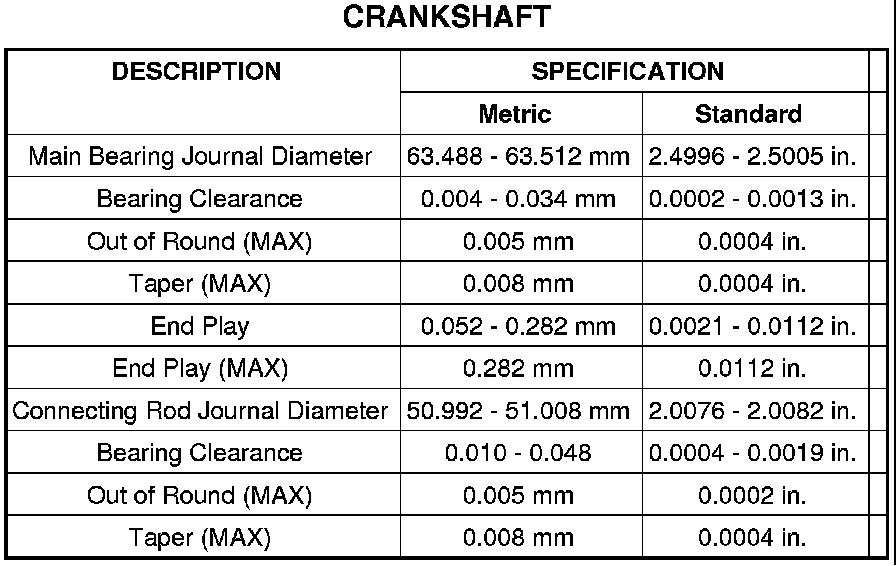
CRANKSHAFT
Crankshaft:
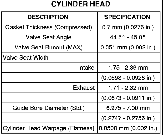
CYLINDER HEAD
Cylinder Head:
MAIN BEARING CAP TORQUE AND SEQUENCE
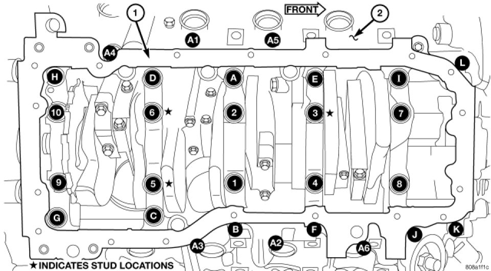
NOTE: Lubricate the bedplate retaining bolts with clean engine oil prior to installation.
6. Install the bedplate retaining bolts, making sure to place the stud bolts in the correct location, Torque the bolts in the sequence shown.
- Tighten bolts A - L to 54 Nm (40 ft. lbs.)
- Tighten bolts 1-10 to 2.8 Nm (25 in. lbs.)
- Turn bolts 1-10 an additional 90°.
- Tighten bolts A1- A6 to 27 Nm (20 ft. lbs.)
CRANKSHAFT MAIN BEARING SELECTION
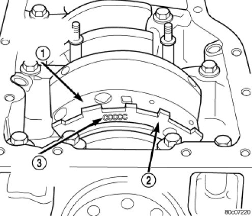
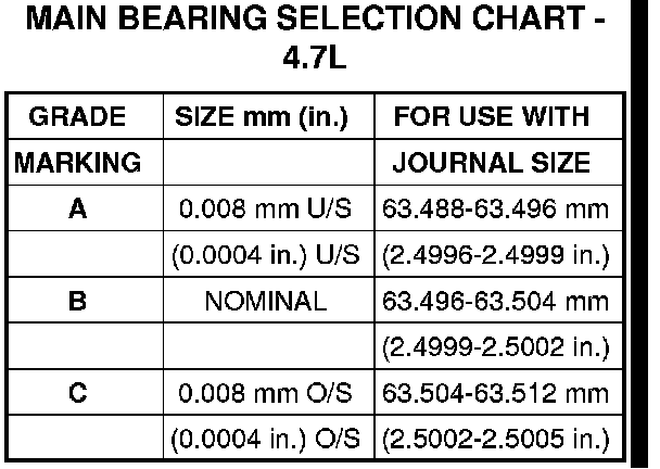
The main bearings are "select fit" to achieve proper oil clearances. For main bearing selection, the crankshaft position sensor target wheel has grade identification marks stamped into it (3). These marks are read from left to right, corresponding with journal number 1, 2, 3, 4 and 5. The crankshaft position sensor target wheel (2) is mounted to the number 8 counter weight (1) on the crankshaft.
NOTE: Service main bearings are coded. These codes identify what size (grade) the bearing is.
HARMONIC BALANCER TORQUE
CAUTION: To prevent severe damage to the Crankshaft, Damper or Special Tool 8512-A, thoroughly clean the damper bore and the crankshaft nose before installing Damper.
1. Align vibration damper slot with key in crankshaft. Slide damper onto crankshaft slightly.
CAUTION: Special Tool 8512-A, is assembled in a specific sequence. Failure to assemble this tool in this sequence can result in tool failure and severe damage to either the tool or the crankshaft.
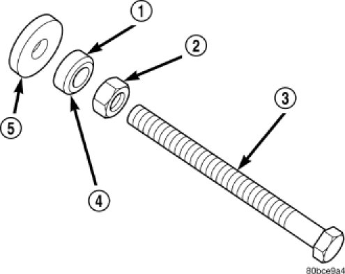
2. Assemble Special Tool 8512-A as follows, The nut (2) is threaded onto the shaft first. Then the roller bearing (1) is placed onto the threaded rod (3) (The hardened bearing surface of the bearing (1) MUST face the nut (2). Then the hardened washer (5) slides onto the threaded rod. Once assembled coat the threaded rod's threads with MOPAR (R) Nickel Anti-Seize or equivalent.
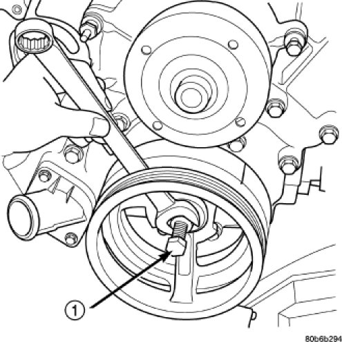
3. Using Special Tool 8512-A, press damper onto crankshaft (1).
4. Install then tighten vibration damper bolt to 175 Nm (130 ft. lbs.).
Factory Service Tools
Use the Manual With the Right Hardware
Pair factory procedures with proven DIY tools so the instructions are easier to execute.
Disclosure: Verified tool recommendations may earn an affiliate commission at no cost to you.
When to See a Mechanic
Stop DIY work and contact a certified mechanic immediately if any of the following apply:
- • You smell fuel, burning insulation, or see smoke.
- • Brakes feel soft, pull hard to one side, or make grinding noises.
- • The engine overheats, stalls repeatedly, or misfires under load.
- • You are missing required tools, torque specs, or safe lifting equipment.
- • You are not confident in the next step or safety outcome.
Rather have a pro handle this?
A certified mobile mechanic comes to your home or office. They bring the tools, you stay comfortable. No tow truck, no waiting room, no surprises.
Comes to youSame-day available12-month warranty
Get a Free QuoteNo obligation. See pricing before you book.