
Safety Warning
DIY auto repair can cause serious injury, fire, or vehicle damage. These guides are for informational purposes only. Always follow OEM torque specs, wear PPE, and consult a certified mechanic if you are unsure. You are solely responsible for your safety.
2008 Jeep Commander 4WD V6-3.7LFACTORY OEM SERVICE PROCEDURE
Installation
INSTALLATION
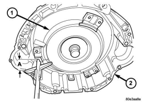
1. Check torque converter hub and hub drive flats for sharp edges burrs, scratches, or nicks. Polish the hub and flats with 320/400 grit paper and crocus cloth if necessary. The hub must be smooth to avoid damaging pump seal at installation.
2. If a replacement transmission is being installed, transfer any components necessary, such as the manual shift lever and shift cable bracket, from the original transmission onto the replacement transmission.
3. Lubricate oil pump seal lip with transmission fluid.
4. Place torque converter in position on transmission.
CAUTION: Do not damage oil pump seal or converter hub while inserting torque converter into the front of the transmission.
5. Align torque converter to oil pump seal opening.
6. Insert torque converter (1) hub into oil pump.
7. While pushing torque converter inward, rotate converter until converter is fully seated in the oil pump gears.
8. Check converter seating with a scale and straightedge. Surface of converter lugs should be at least 19 mm (3/4 in.) to rear of straightedge when converter is fully seated.
9. If necessary, temporarily secure converter with C-clamp attached to the converter housing.
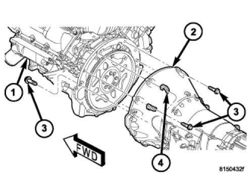
10. Check condition of converter driveplate. Replace the plate if cracked, distorted or damaged. Also be sure transmission dowel pins are seated in engine block and protrude far enough to hold transmission in alignment.
11. Apply a light coating of Mopar(R) High Temp Grease to the torque converter hub pocket in the rear pocket of the engine's crankshaft.
12. Raise transmission and align the torque converter with the drive plate and the transmission converter housing with the engine block.
13. Move transmission forward. Then raise, lower, or tilt transmission to align the converter housing with the engine block dowels.
14. Carefully work transmission (2) forward and over engine (1) block dowels until converter hub is seated in crankshaft. Verify that no wires, or the transmission vent hose, have become trapped between the engine block and the transmission.
15. Install two bolts (3) to attach the transmission to the engine.
16. Install remaining torque converter housing to engine bolts. Tighten to 39 Nm (29 ft.lbs.).
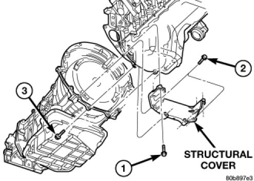
17. Install rear transmission crossmember. Tighten crossmember to frame bolts to 68 Nm (50 ft.lbs.).
18. Install rear support to transmission. Tighten bolts to 47 Nm (35 ft.lbs.).
19. Lower transmission onto crossmember and install bolts attaching transmission mount to crossmember. Tighten clevis bracket to crossmember bolts to 47 Nm (39 ft.lbs.). Tighten the clevis bracket to rear support bolt to 68 Nm (50 ft.lbs.).
20. Remove engine support fixture.
21. Install the engine to transmission structural cover. Structural Dust Cover - Installation
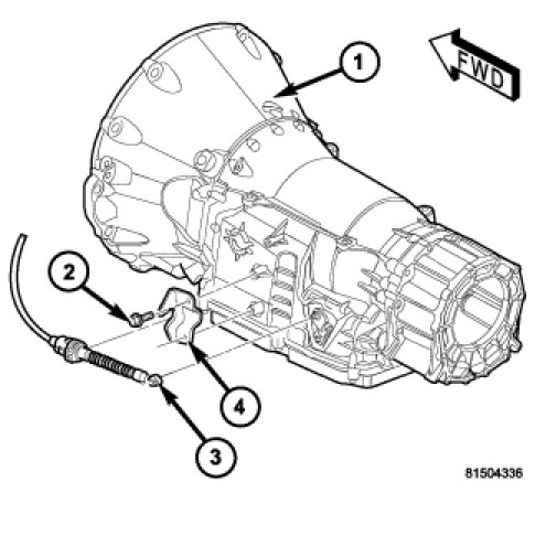
22. Connect gearshift cable (3) to the gearshift cable bracket (4) and transmission (1).
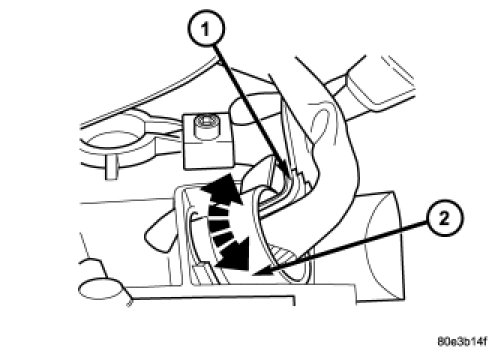
23. Check O-ring on plug connector (1) , and replace if necessary.
24. Install the plug connector (1) into the adapter plug (2). Turn bayonet lock of the adapter plug (2) clockwise to connect plug connector (1).
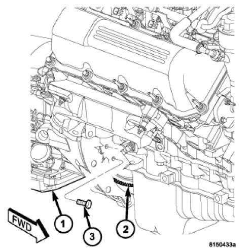
CAUTION: It is essential that correct length bolts be used to attach the converter to the driveplate. Bolts that are too long will damage the clutch surface inside the converter.
25. For gas engines, install all torque converter-to-driveplate bolts (3) by hand.
26. Verify that the torque converter is pulled flush to the driveplate. Tighten bolts to 42 Nm (31 ft. lbs.).
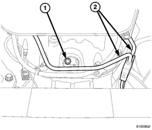
CAUTION: It is essential that correct length bolts be used to attach the converter to the driveplate. Bolts that are too long will damage the clutch surface inside the converter.
27. For diesel engines, install all torque converter-to-driveplate bolts (1) by hand.
28. Verify that the torque converter is pulled flush to the driveplate. Tighten bolts to 42 Nm (31 ft. lbs.).
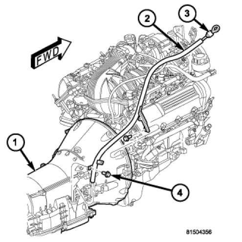
29. Install starter motor. Starter Motor - Installation
30. Install transmission fill tube (2).
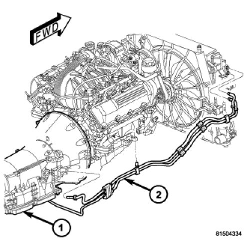
31. Connect cooler lines (2) to transmission (1).
32. Install exhaust components.
33. Install transfer case, if necessary. Transfer Case - Removal
34. Align and connect propeller shafts. Propeller Shaft - Installation
35. Adjust gearshift cable if necessary.Adjustments
36. Lower vehicle.
37. Connect negative battery cable.
38. Fill transmission with the appropriate fluid Transmission Fill - NAG1.
39. Verify proper operation.
Factory Service Tools
Use the Manual With the Right Hardware
Pair factory procedures with proven DIY tools so the instructions are easier to execute.
Disclosure: Verified tool recommendations may earn an affiliate commission at no cost to you.
When to See a Mechanic
Stop DIY work and contact a certified mechanic immediately if any of the following apply:
- • You smell fuel, burning insulation, or see smoke.
- • Brakes feel soft, pull hard to one side, or make grinding noises.
- • The engine overheats, stalls repeatedly, or misfires under load.
- • You are missing required tools, torque specs, or safe lifting equipment.
- • You are not confident in the next step or safety outcome.
Rather have a pro handle this?
A certified mobile mechanic comes to your home or office. They bring the tools, you stay comfortable. No tow truck, no waiting room, no surprises.
Comes to youSame-day available12-month warranty
Get a Free QuoteNo obligation. See pricing before you book.