
Safety Warning
DIY auto repair can cause serious injury, fire, or vehicle damage. These guides are for informational purposes only. Always follow OEM torque specs, wear PPE, and consult a certified mechanic if you are unsure. You are solely responsible for your safety.
2008 Jeep Commander 4WD V6-3.7LFACTORY OEM SERVICE PROCEDURE
Assembly
ASSEMBLY
CAUTION: Make certain all valves and springs are assembled correctly. Failure to follow this caution may result in transmission failure.
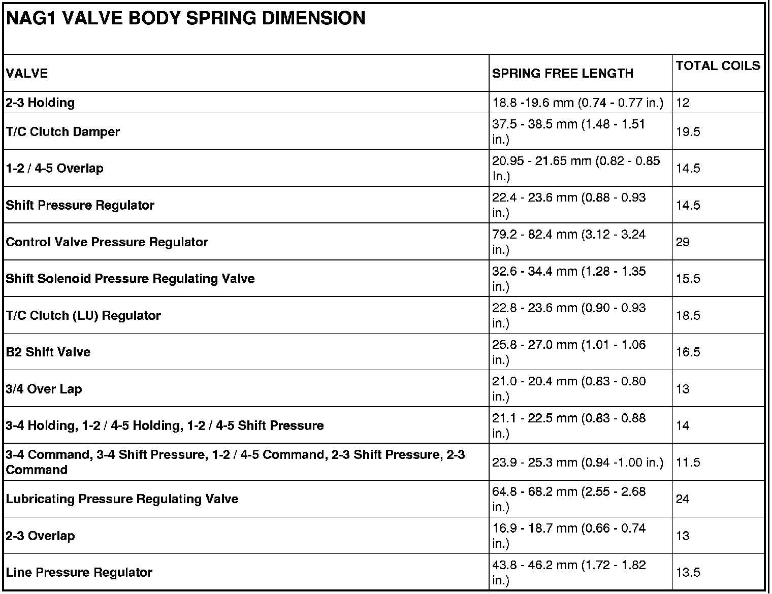
NOTE: Pay great attention to cleanliness for all work on the shift plate. Fluffy cloths must not be used. Leather cloths are particularly good. After dismantling, all parts must be washed and blown out with compressed-air, noting that parts may be blown away.
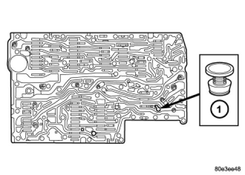
1. Install the pressure supply valve (1) into the valve body.
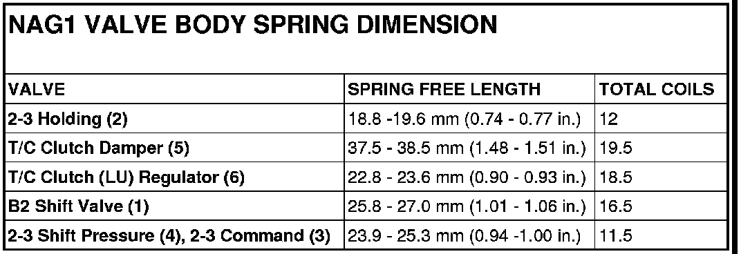
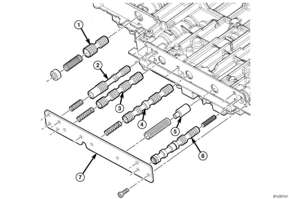
2. Lubricate and install the B-2 Shift Valve assembly (1), 2-3 Holding Pressure Valve assembly (2), 2-3 Command Valve assembly (3), 2-3 Shift Pressure Shift Valve assembly (4), TCC Damper Valve (5) if equipped and the T/CC Lock-Up Regulator Valve assembly (6) into the valve body.
3. Install the side cover and the screws holding the side cover (7) to the valve body and valve housing. Tighten the screws to 4 Nm (35 in.lbs.).
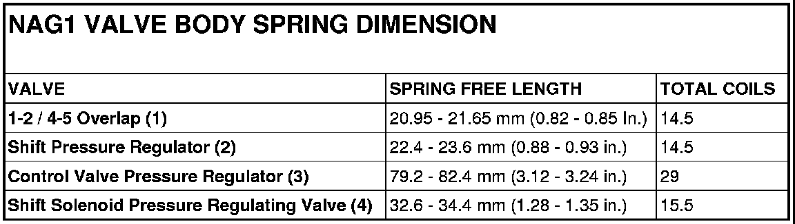
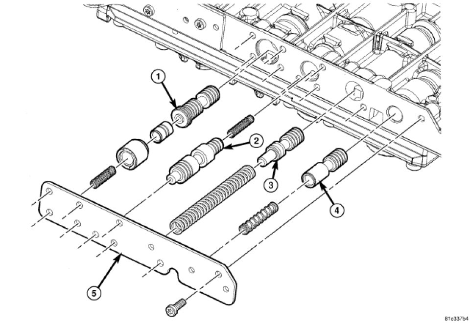
4. Lubricate and install the 1-2 / 4-5 Overlap Regulating Valve, Sleeve, and Piston assembly (1), Shift Pressure Regulating Valve assembly (2), Control Valve Pressure Regulator Valve assembly (3) and Shift Solenoid Pressure Regulating Valve assembly (4) into the valve body.
5. Install the side cover and the screws holding the side cover (5) to the valve body and valve housing. Tighten the screws to 4 Nm (35 in.lbs.).
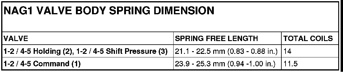
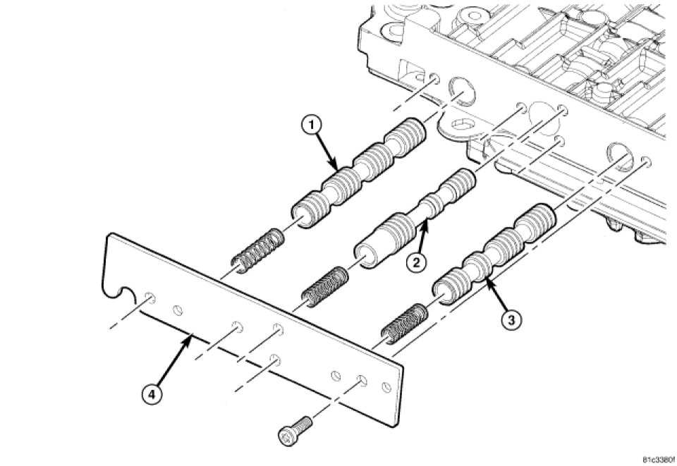
6. Lubricate and install the 1-2 / 4-5 Command valve assembly (1), 1-2 / 4-5 Holding Pressure Shift Valve (2) and the 1-2 / 4-5 Shift Pressure assembly (3) into the valve body.
7. Install the side cover and the screws holding the side cover (4) to the valve body and valve housing. Tighten the screws to 4 Nm (35 in.lbs.).
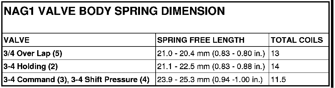
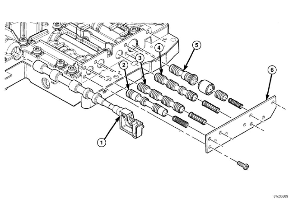
8. Lubricate and install the sector valve (1).
9. Lubricate and install 3-4 Holding Pressure Shift Valve assembly (2), 3-4 Command Valve assembly (3), 3-4 Shift Pressure assembly (4) and the 3-4 Overlap Regulating Valve Sleeve and Piston assembly (5) into the valve body.
10. Install the side cover and the screws holding the side cover (6) to the valve body and valve housing. Tighten the screws to 4 Nm (35 in.lbs.).
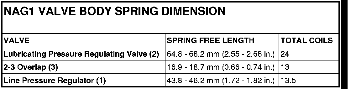
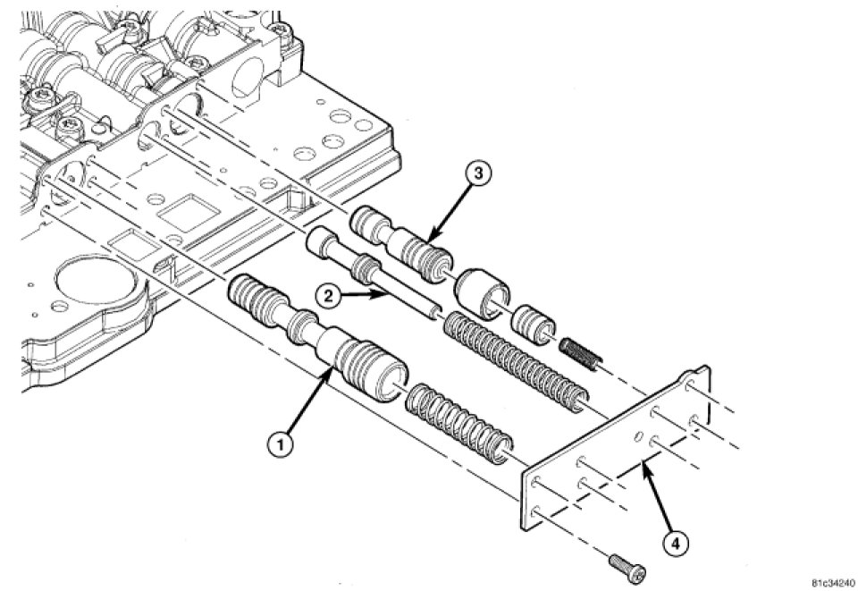
11. Lubricate and install the Operating Pressure Regulating Valve assembly (1), Lubricating Pressure Regulating Valve assembly (2) and the 2-3 Overlap Regulating Valve, Sleeve and Piston assembly (3) into the valve body.
12. Install the side cover and the screws holding the side cover (6) to the valve body and valve housing. Tighten the screws to 4 Nm (35 in.lbs.).
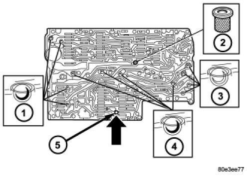
NOTE: A total of 12 valve balls are located in the valve body, four made from plastic (4) and eight from steel (1, 3).
13. Install all check balls (1, 3, 4) and the central strainer (2).
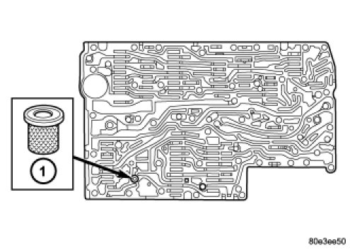
14. Install the strainer (1) in the inlet to torque converter lock-up control solenoid valve.
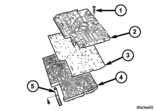
15. Position the sealing plate (3) onto the valve body (4).
16. Install the valve housing (2) onto the valve body (4) and sealing plate (3).
17. Install the shift plate Torx(R) bolts (1). Tighten the bolts to 8 Nm (71 in.lbs.).
18. Install leaf spring (5).
19. Install the strainers (1) for the modulating pressure and shift pressure control solenoid valves into the valve housing.
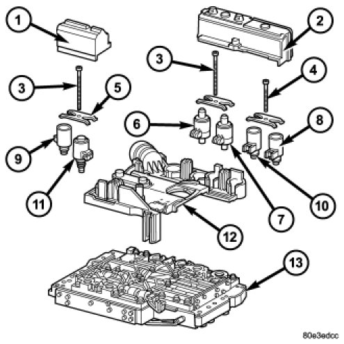
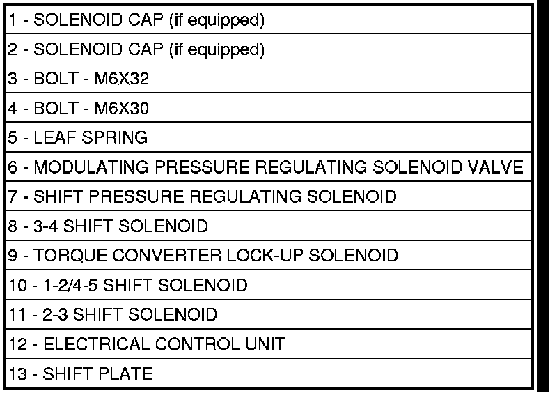
20. Install the electrohydraulic control module (12) onto the shift plate (13).
21. Bend the retaining lug on stiffening rib on transmission oil temperature sensor to retain the electrohydraulic control module.
22. Install the solenoid valves (6 - 11) into shift plate (13).
NOTE: Check O-rings on solenoid valves for damage and replace if necessary.
23. Install the leaf springs (5).
24. Install the Torx(R) socket bolts (3, 4). Tighten the bolts to 8 Nm (71 in.lbs.).
NOTE: Pay attention to the different lengths of the Torx(R) socket bolts.
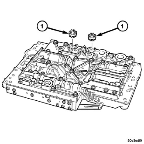
25. Install the solenoid caps (1, 2) if equipped.
26. Install the electrohydraulic unit into the vehicle.
Factory Service Tools
Use the Manual With the Right Hardware
Pair factory procedures with proven DIY tools so the instructions are easier to execute.
Disclosure: Verified tool recommendations may earn an affiliate commission at no cost to you.
When to See a Mechanic
Stop DIY work and contact a certified mechanic immediately if any of the following apply:
- • You smell fuel, burning insulation, or see smoke.
- • Brakes feel soft, pull hard to one side, or make grinding noises.
- • The engine overheats, stalls repeatedly, or misfires under load.
- • You are missing required tools, torque specs, or safe lifting equipment.
- • You are not confident in the next step or safety outcome.
Rather have a pro handle this?
A certified mobile mechanic comes to your home or office. They bring the tools, you stay comfortable. No tow truck, no waiting room, no surprises.
Comes to youSame-day available12-month warranty
Get a Free QuoteNo obligation. See pricing before you book.