
Safety Warning
DIY auto repair can cause serious injury, fire, or vehicle damage. These guides are for informational purposes only. Always follow OEM torque specs, wear PPE, and consult a certified mechanic if you are unsure. You are solely responsible for your safety.
2008 Jeep Commander 4WD V6-3.7LFACTORY OEM SERVICE PROCEDURE
Assembly
ASSEMBLY
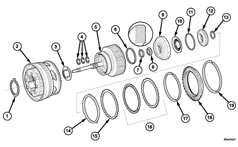
Input Clutch K2 Components
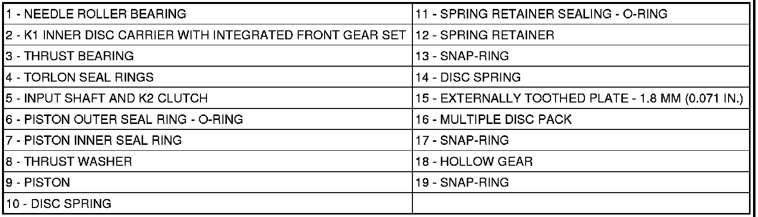
1. Install piston (9) in outer multiple-disc carrier. Inspect seals (6 and 7), replace if necessary. The rounded edges of the inner piston seal (7) must point to the outside.
2. Insert disk spring (10) and spring retainer (12). Insert disk spring (10) with curved side pointing toward spring retainer (12). Inspect seal (11), replace if necessary.
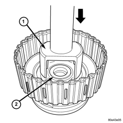
3. Place Multi-use Spring Compressor 8900 (1) on spring plate and press until the groove (2) of the snap-ring is exposed.
4. Insert snap-ring.
5. Insert disk spring (14).
NOTE: Pay attention to the sequence of discs. If the original clutch discs are reused, be sure to return the disc identified on disassembly as belonging on top of the disc spring (14) to its original location.
6. Insert multiple-disk set (16) into outer multiple-disk carrier.
7. Fit snap-ring (17).
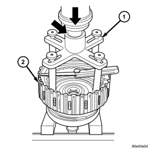
8. Measure K2 clutch clearance by mounting Pressing Tool 8901-A (1) on outer multiple disc.
9. Using a lever press, compress pressing tool to the upper most line marked 1200 N (the marking ring is still visible, see small arrow).
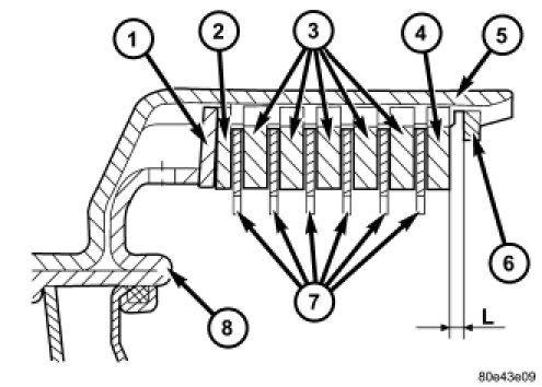
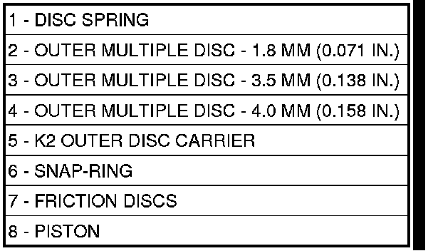
10. Using a feeler gauge, determine the play "L" at three points between the snap-ring (6) and outer multiple-disc (4).
11. During the measurement the snap-ring (6) must contact the upper bearing surface of the groove in the outer multiple-disc carrier.
12. The correct clutch clearance is 2.3-2.7 mm (0.091-0.106 in.) for three friction disc versions, 2.4-2.8 mm (0.095-0.110 in.) for four disc versions, 2.5-2.9 mm (0.099-0.114 in.) for five disc versions, and 2.7-3.1 mm (0.106-0.122 in.) for six disc versions.
13. Adjust with snap-ring (6), if necessary. Snap-rings are available in thicknesses of 2.3 mm (0.091 in.), 2.6 mm (0.102 in.), 2.9 mm (0.114 in.), 3.2 mm (0.126 in.), 3.5 mm (0.138 in.), and 3.8 mm (0.150 in.).
Input Clutch K2 Components
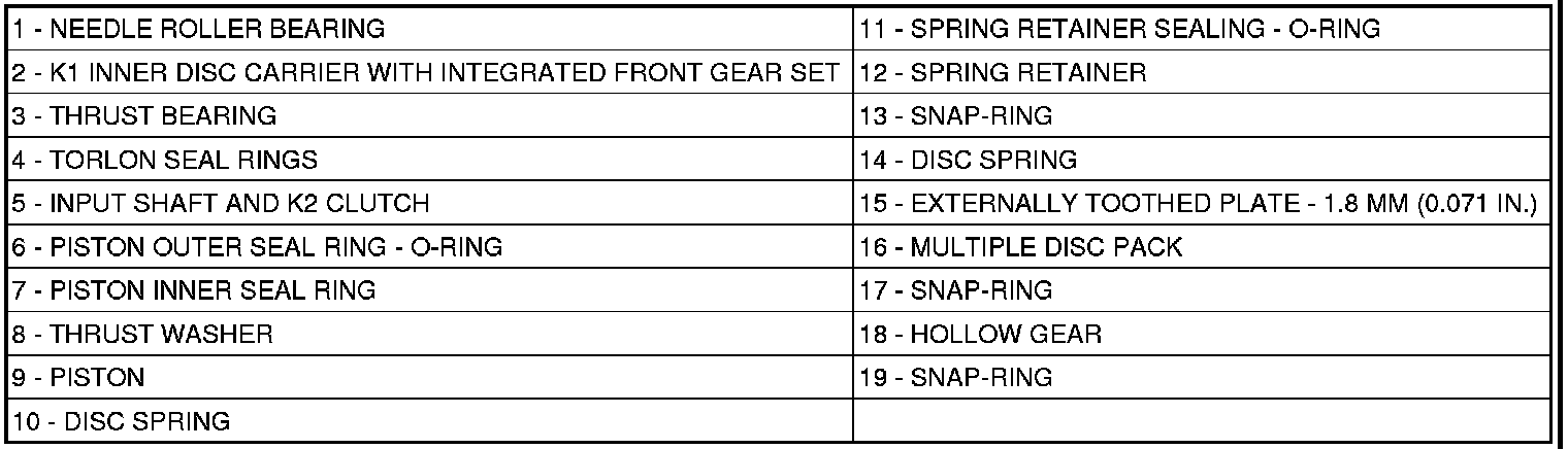
14. Insert axial needle bearing (3) into K1 inner multiple-disk carrier. Insert axial needle bearing (3) with a little grease to prevent it slipping.
15. Install input shaft in K1 inner multiple-disc carrier with integrated front gear set (2).
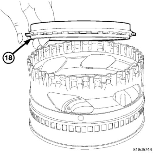
NOTE: Insure that the Hollow Gear (18) is oriented during installation such it protrudes from the K2 Retainer.
16. Fit internally-geared wheel (18) and install snap-ring.
Factory Service Tools
Use the Manual With the Right Hardware
Pair factory procedures with proven DIY tools so the instructions are easier to execute.
Disclosure: Verified tool recommendations may earn an affiliate commission at no cost to you.
When to See a Mechanic
Stop DIY work and contact a certified mechanic immediately if any of the following apply:
- • You smell fuel, burning insulation, or see smoke.
- • Brakes feel soft, pull hard to one side, or make grinding noises.
- • The engine overheats, stalls repeatedly, or misfires under load.
- • You are missing required tools, torque specs, or safe lifting equipment.
- • You are not confident in the next step or safety outcome.
Rather have a pro handle this?
A certified mobile mechanic comes to your home or office. They bring the tools, you stay comfortable. No tow truck, no waiting room, no surprises.
Comes to youSame-day available12-month warranty
Get a Free QuoteNo obligation. See pricing before you book.