
Safety Warning
DIY auto repair can cause serious injury, fire, or vehicle damage. These guides are for informational purposes only. Always follow OEM torque specs, wear PPE, and consult a certified mechanic if you are unsure. You are solely responsible for your safety.
2007 Jeep Commander 2WD V8-5.7L VIN 2FACTORY OEM SERVICE PROCEDURE
Steering Mounted Controls Communication Module
Component ID: 208
Component : MODULE-STEERING CONTROL
Connector:
Name : MODULE-STEERING CONTROL C1
Color :
# of pins : 16
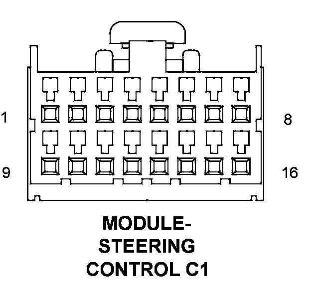
Pin Description Circuit
1 - -
2 CAN C BUS (+) D65 20WT/LG
3 CAN C BUS (-) D64 20WT/LB
4 - -
5 GROUND Z907 20BK
6 CAN B BUS (+) D55 20WT/OR
7 CAN B BUS (-) D54 20WT
8 FUSED B(+) A108 20LG/RD
9 S/C SWITCH RETURN V937 20VT/BR
10 S/C SWITCH SENSE 1 V71 20VT/OR
11 S/C SWITCH SENSE 2 V72 20OR/VT
12 REAR WIPER MOTOR CONTROL W13 20BR/LG
13 REAR WIPER MOTOR DELAY SIGNAL W14 20BR/LB
14 IGNITION SWITCH SENSE G20 20VT/BR
15 IGNITION SWITCH SENSE RETURN G900 20VT/OR
16 HAZARD SWITCH SENSE L91 20WT/DB
Component Location - 45
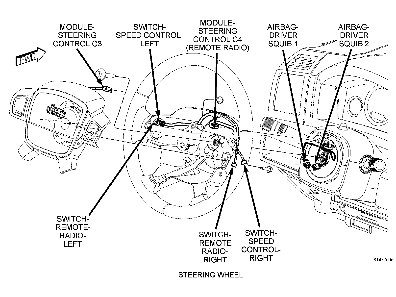
Connector:
Name : MODULE-STEERING CONTROL C2
Color : YELLOW
# of pins : 4
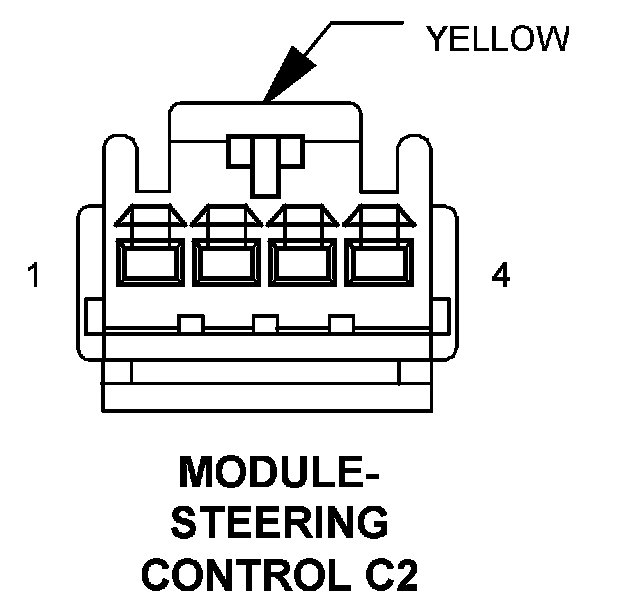
Pin Description Circuit
1 DRIVER SQUIB 2 LINE 2 R61 20LG/VT
2 DRIVER SQUIB 2 LINE 1 R63 20LG/WT
3 DRIVER SQUIB 1 LINE 2 R43 20LG/BR
4 DRIVER SQUIB 1 LINE 1 R45 20LG/OR
Component Location - 45
Connector:
Name : MODULE-STEERING CONTROL C3
Color : NATURAL
# of pins : 6
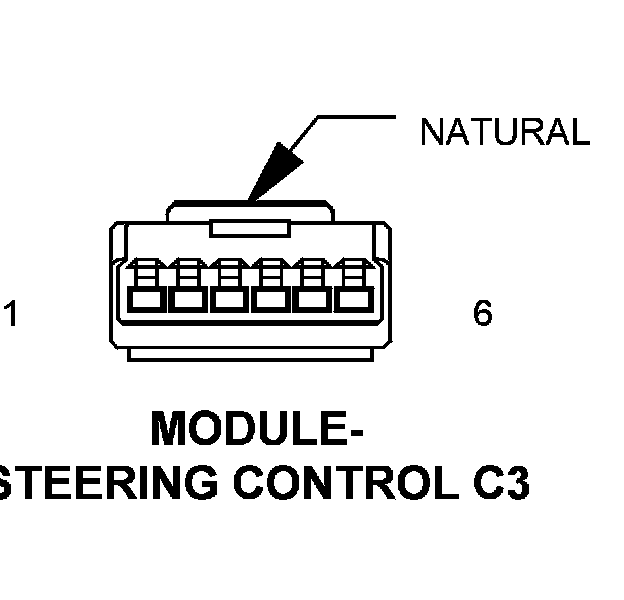
Pin Description Circuit
1 - -
2 S/C SWITCH RETURN V397 20VT/BR
3 S/C SWITCH NO. 1 SIGNAL V371 20VT/OR
4 S/C SWITCH NO. 2 SIGNAL V372 20OR/VT
5 HORN SWITCH SIGNAL X3 20DG/VT
6 HORN SWITCH RETURN X903 20GY/LG
Component Location - 45
Connector:
Name : MODULE-STEERING CONTROL C4
Color : BLACK
# of pins : 2
Qualifier : (REMOTE RADIO)
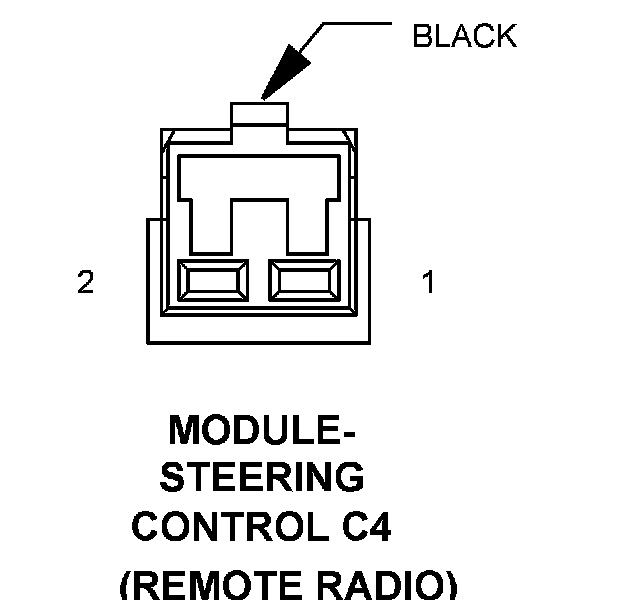
Pin Description Circuit
1 RADIO CONTROL MUX X20 20GY/WT
2 RADIO CONTROL MUX RETURN X920 20GY/OR
Component Location - 45
Connector:
Name : MODULE-STEERING CONTROL C5
Color : BLACK/YELLOW
# of pins : 2
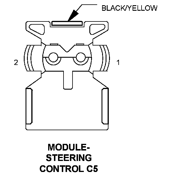
Pin Description Circuit
1 DRIVER SQUIB 1 LINE 1 R345 20LG/OR
2 DRIVER SQUIB 1 LINE 2 R343 20LG/BR
Component Location - 45
Connector:
Name : MODULE-STEERING CONTROL C6
Color : BROWN/YELLOW
# of pins : 2
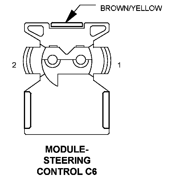
Pin Description Circuit
1 DRIVER SQUIB 2 LINE 1 R363 20LG/WT
2 DRIVER SQUIB 2 LINE 2 R361 20LG/VT
Component Location - 45
Factory Service Tools
Use the Manual With the Right Hardware
Pair factory procedures with proven DIY tools so the instructions are easier to execute.
Disclosure: Verified tool recommendations may earn an affiliate commission at no cost to you.
When to See a Mechanic
Stop DIY work and contact a certified mechanic immediately if any of the following apply:
- • You smell fuel, burning insulation, or see smoke.
- • Brakes feel soft, pull hard to one side, or make grinding noises.
- • The engine overheats, stalls repeatedly, or misfires under load.
- • You are missing required tools, torque specs, or safe lifting equipment.
- • You are not confident in the next step or safety outcome.