
Safety Warning
DIY auto repair can cause serious injury, fire, or vehicle damage. These guides are for informational purposes only. Always follow OEM torque specs, wear PPE, and consult a certified mechanic if you are unsure. You are solely responsible for your safety.
2001 Isuzu Rodeo LS 2WD V6-3.2LFACTORY OEM SERVICE PROCEDURE
Shift Light: Testing and Inspection
Upshift Lamp System Check (Manual Transmisssion Only)
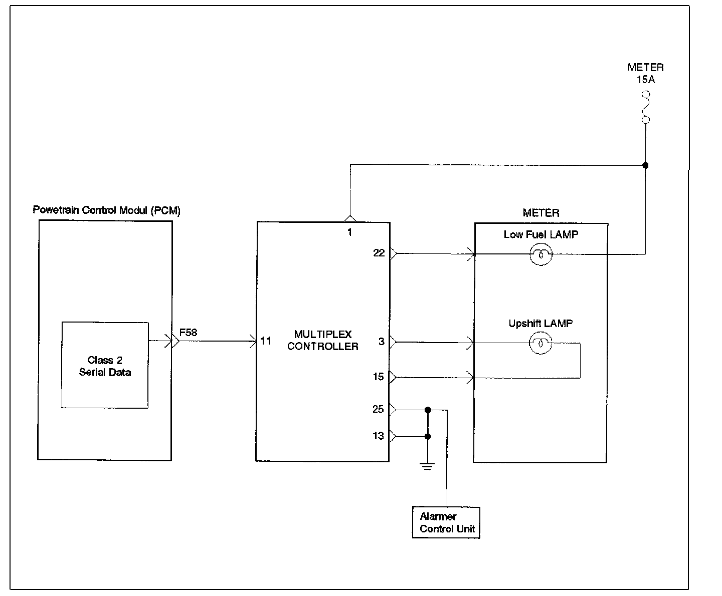
Circuit Description
The Upshift Lamp should always be illuminated and steady with the ignition "ON" and the engine stopped. Ignition feed voltage is supplied to the Upshift Lamp bulb through the meter fuse. The powertrain control module (PCM) orders the Upshift Lamp "ON" signal for Multiplex Control Unit. When Multiplex Control Unit is received Upshift Lamp "ON" signal that turn Upshift Lamp "ON" by grounding the Upshift Lamp driver circuit.
Diagnostic Aids
An intermittent Upshift Lamp may be cased by a poor connection, rubbed-through wire insulation, or a wire broken inside the insulation. Check for the following items:
- Inspect the PCM and Multiplex Control Unit harness and connections for improper mating, broken locks, improperly formed or damaged terminals, poor terminal-to-wire connection, and damaged harness.
- If the engine runs OK, check for a faulty light bulb, an open in the MIL driver circuit, or an open in the instrument cluster ignition feed.
- If the engine cranks but will not run, check for an open PCM ignition or battery feed, or a poor PCM to engine ground.
Test Description
Circuit Description
The Upshift Lamp should always be illuminated and steady with the ignition "ON" and the engine stopped. Ignition feed voltage is supplied to the Upshift Lamp bulb through the meter fuse. The powertrain control module (PCM) orders the Upshift Lamp "ON" signal for Multiplex Control Unit. When Multiplex Control Unit is received Upshift Lamp "ON" signal that turn Upshift Lamp "ON" by grounding the Upshift Lamp driver circuit.
Diagnostic Aids
An intermittent Upshift Lamp may be cased by a poor connection, rubbed-through wire insulation, or a wire broken inside the insulation. Check for the following items:
- Inspect the PCM and Multiplex Control Unit harness and connections for improper mating, broken locks, improperly formed or damaged terminals, poor terminal-to-wire connection, and damaged harness.
- If the engine runs OK, check for a faulty light bulb, an open in the MIL driver circuit, or an open in the instrument cluster ignition feed.
- If the engine cranks but will not run, check for an open PCM ignition or battery feed, or a poor PCM to engine ground.
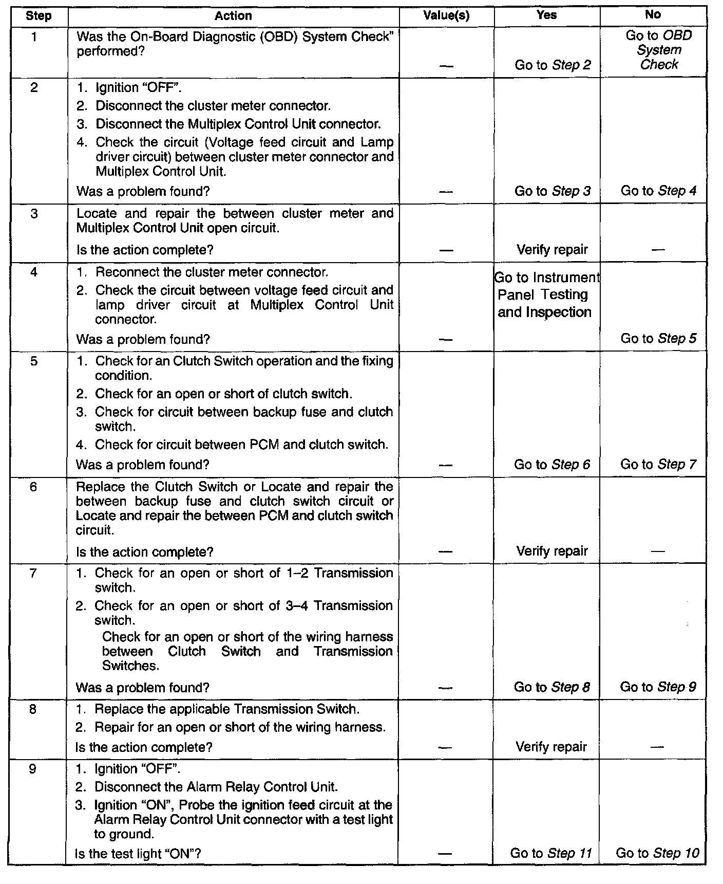
Steps 1 - 9:
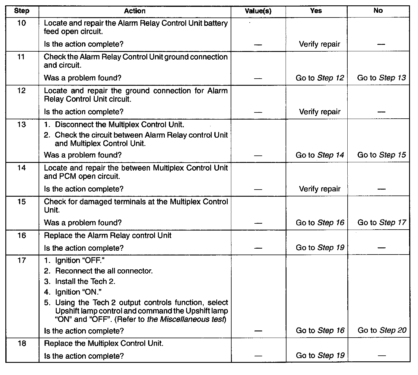
Steps 10 - 18:
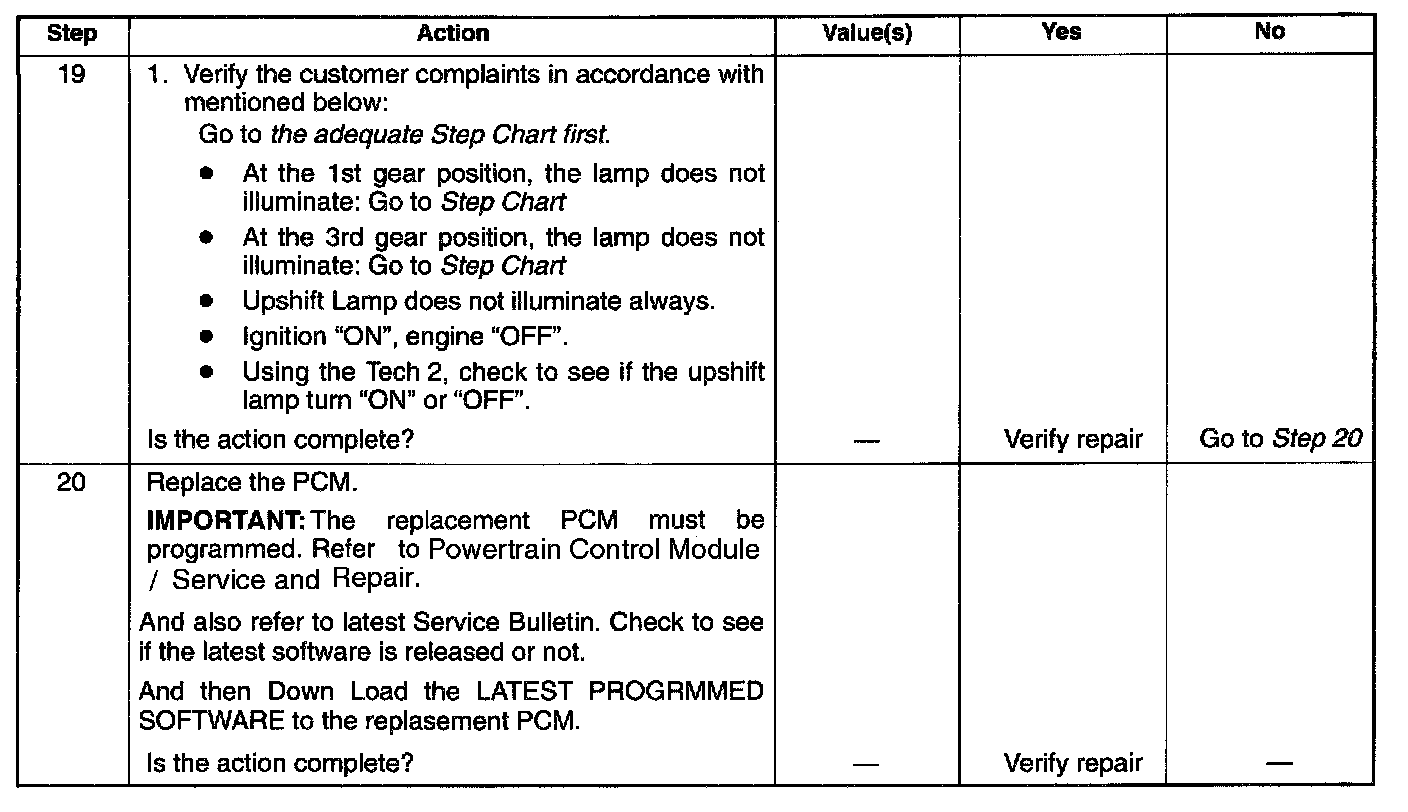
Steps 19 - 20:
Test Description
Factory Service Tools
Use the Manual With the Right Hardware
Pair factory procedures with proven DIY tools so the instructions are easier to execute.
Disclosure: Verified tool recommendations may earn an affiliate commission at no cost to you.
When to See a Mechanic
Stop DIY work and contact a certified mechanic immediately if any of the following apply:
- • You smell fuel, burning insulation, or see smoke.
- • Brakes feel soft, pull hard to one side, or make grinding noises.
- • The engine overheats, stalls repeatedly, or misfires under load.
- • You are missing required tools, torque specs, or safe lifting equipment.
- • You are not confident in the next step or safety outcome.