
Safety Warning
DIY auto repair can cause serious injury, fire, or vehicle damage. These guides are for informational purposes only. Always follow OEM torque specs, wear PPE, and consult a certified mechanic if you are unsure. You are solely responsible for your safety.
2000 Isuzu Rodeo S 2WD V6-3.2LFACTORY OEM SERVICE PROCEDURE
Service Specifications
Connecting Rods

1. Check the connecting rod alignment If either the bend or the twist exceeds the specified limit, the connecting rod must be replaced.
Bend per 100 mm (3.937 inch)
Limit: 0.15 (0.0059)
Twist per 100 mm (3.937 inch)
Limit: 0.20 (0.0078)

2. Measure the connecting rod thrust clearance. Use a feeler gauge to measure the thrust clearance at the large end of the connecting rod If the clearance exceeds the specified limit, the connecting rod must be replaced.
Standard: 0.16 mm - 0.35 mm (0.0063 inch - 0.0138 inch)
Limit: 0.40 mm (0.0157 inch)
3. Measure the oil clearance between the connecting rod and the crankshaft.
a. Remove the connecting rod cap nuts and the rod caps (12).
Arrange the removed rod caps in the cylinder number order.
b. Clean the rod bearings and the crankshaft pins.

c. Carefully check the rod bearings. If even one bearing is found to be damaged or badly worn, the entire bearing assembly must be replaced as a set. Reinstall the bearings in their original positions. Apply plastigage to the crank pin.
d. Reinstall the rod caps (12) to their original positions.
Tighten the rod cap nuts.
Torque: 54 Nm (40 ft. lbs.)
Note: Do not allow the crankshaft to rotate.
e. Remove the rod caps.
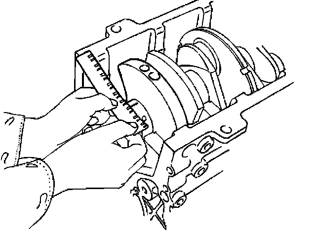
f. Measure the width of the plastigage and determine the oil clearance. If the oil clearance exceeds the limit, replace the rod bearing as a set.
Standard: 0.019 mm - 0.043 mm (0.0007 inch - 0.0017 inch)
Limit: 0.08 mm (0.003 inch)
g. Clean the plastigage from the bearings and the crankshaft pins.
Connnecting Rod Bearing Selection
Select and install the new connecting rod bearings, paying close attention to the connecting rod big end diameter size mark (1).


Note: Take care not to confuse the alignment mark (2) and the size mark (1) during the installation procedure.
1. Check the connecting rod alignment If either the bend or the twist exceeds the specified limit, the connecting rod must be replaced.
Bend per 100 mm (3.937 inch)
Limit: 0.15 (0.0059)
Twist per 100 mm (3.937 inch)
Limit: 0.20 (0.0078)
2. Measure the connecting rod thrust clearance. Use a feeler gauge to measure the thrust clearance at the large end of the connecting rod If the clearance exceeds the specified limit, the connecting rod must be replaced.
Standard: 0.16 mm - 0.35 mm (0.0063 inch - 0.0138 inch)
Limit: 0.40 mm (0.0157 inch)
3. Measure the oil clearance between the connecting rod and the crankshaft.
a. Remove the connecting rod cap nuts and the rod caps (12).
Arrange the removed rod caps in the cylinder number order.
b. Clean the rod bearings and the crankshaft pins.
c. Carefully check the rod bearings. If even one bearing is found to be damaged or badly worn, the entire bearing assembly must be replaced as a set. Reinstall the bearings in their original positions. Apply plastigage to the crank pin.
d. Reinstall the rod caps (12) to their original positions.
Tighten the rod cap nuts.
Torque: 54 Nm (40 ft. lbs.)
Note: Do not allow the crankshaft to rotate.
e. Remove the rod caps.
f. Measure the width of the plastigage and determine the oil clearance. If the oil clearance exceeds the limit, replace the rod bearing as a set.
Standard: 0.019 mm - 0.043 mm (0.0007 inch - 0.0017 inch)
Limit: 0.08 mm (0.003 inch)
g. Clean the plastigage from the bearings and the crankshaft pins.
Connnecting Rod Bearing Selection
Select and install the new connecting rod bearings, paying close attention to the connecting rod big end diameter size mark (1).
Bearing Selection Chart:
Note: Take care not to confuse the alignment mark (2) and the size mark (1) during the installation procedure.
Factory Service Tools
Use the Manual With the Right Hardware
Pair factory procedures with proven DIY tools so the instructions are easier to execute.
Disclosure: Verified tool recommendations may earn an affiliate commission at no cost to you.
When to See a Mechanic
Stop DIY work and contact a certified mechanic immediately if any of the following apply:
- • You smell fuel, burning insulation, or see smoke.
- • Brakes feel soft, pull hard to one side, or make grinding noises.
- • The engine overheats, stalls repeatedly, or misfires under load.
- • You are missing required tools, torque specs, or safe lifting equipment.
- • You are not confident in the next step or safety outcome.
Rather have a pro handle this?
A certified mobile mechanic comes to your home or office. They bring the tools, you stay comfortable. No tow truck, no waiting room, no surprises.
Comes to youSame-day available12-month warranty
Get a Free QuoteNo obligation. See pricing before you book.