1993 Infiniti G20 AutomaticFACTORY OEM SERVICE PROCEDURE

Sensor Range Charts

Sensor operating range information can help determine if a sensor is out of calibration. An out-of-calibration sensor may not set a trouble code, but it may cause driveability problems.

NOTE: Unless stated otherwise in test procedure, perform all voltage tests using a Digital Volt-Ohmmeter (DVOM) with a minimum 10-megohm input impedance.
COOLANT TEMPERATURE SENSOR RESISTANCE (1)

Temperature - Β°F (Β°C) Ohms
68 (20) 2100-2900
122 (50) 680-1000
176 (80) 300-330
(1) Measure resistance across sensor terminals.
EGR TEMPERATURE SENSOR RESISTANCE (1)

Temperature - Β°F (Β°C) Ohms
212 (100) 76,770-93,830
(1) Heat sensor in water and measure resistance across sensor terminals.
FUEL TEMPERATURE SENSOR RESISTANCE (M30 & Q45) (1)

Temperature - Β°F (Β°C) Ohms
68 (20) 2100-2900
122 (50) 680-1000
176 (80) 300-330
(1) Measure resistance between sensor terminals at pressure regulator.
HEATED OXYGEN SENSOR VOLTAGE (1)

Condition Volts
Lean 0-0.3
Rich 0.6-1.0
(1) Measure voltage between oxygen sensor terminal and ground, voltage should continuously change. Measure heater resistance between terminals "A" and "C" at sensor. Resistance should be 3-1000 ohms.
CLOSED & WIDE OPEN THROTTLE SWITCH CONTINUITY (1) (G20) (2)

Position Reading
Closed Throttle Blue/Orange & White Green
Wide Open Throttle Blue/Orange & Blue Red
(1) Continuity should be present between terminals identified by wire color.
(2) Applicable to A/T vehicles produced from serial No. 450021 and later.
CLOSED THROTTLE POSITION SWITCH CONTINUITY (J30 & Q45) (1)

Position Reading
Closed Throttle Continuity
Open Throttle No Continuity
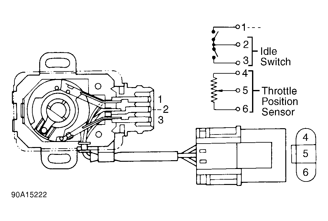
(1) Check continuity between terminals No. 2 and 3 at sensor. See Fig 1 .
THROTTLE POSITION SENSOR RESISTANCE (1)

Position Ohms
G20
Closed Throttle 2000
Partially Open 2000-10,000
Wide Open Throttle 10,000
J30
Closed Throttle 1700
Partially Open 1700-10500
Wide Open Throttle 10500
Q45
Closed Throttle 700
Partially Open 700-5000
Wide Open Throttle 5000
(1) Measure resistance between terminals No. 4 and 5 at sensor. See Fig 1 .
MASS AIRFLOW SENSOR VOLTAGE (LOW RPM) (1)

Application Terminal No Volts
G20 "A" 1.3-1.7
J30 "B" 1.0-1.4
Q45 "1" 1.0-1.4
(1) Measure voltage between ground and indicated airflow meter terminal with engine idling at normal operating temperature.
MASS AIRFLOW SENSOR VOLTAGE (HIGH RPM) (1)

Application Terminal No Volts
G20 "A" 1.7-2.1
J30 "B" 1.4-1.9
Q45 "1" 1.4-1.9
(1) Measure voltage between ground and indicated airflow meter terminal with engine running at 2000 RPM at normal operating temperature.
Fig 1: Throttle Position Sensor/Closed Throttle Switch Terminal ID
G90A15222Courtesy of NISSAN MOTOR CO., U.S.A.
Factory Service Tools

Use the Manual With the Right Hardware

Pair factory procedures with proven DIY tools so the instructions are easier to execute.

Disclosure: Verified tool recommendations may earn an affiliate commission at no cost to you.

When to See a Mechanic

Stop DIY work and contact a certified mechanic immediately if any of the following apply:

  • β€’ You smell fuel, burning insulation, or see smoke.
  • β€’ Brakes feel soft, pull hard to one side, or make grinding noises.
  • β€’ The engine overheats, stalls repeatedly, or misfires under load.
  • β€’ You are missing required tools, torque specs, or safe lifting equipment.
  • β€’ You are not confident in the next step or safety outcome.

Rather have a pro handle this?

A certified mobile mechanic comes to your home or office. They bring the tools, you stay comfortable. No tow truck, no waiting room, no surprises.

Comes to youSame-day available12-month warranty
Get a Free Quote

No obligation. See pricing before you book.