
Safety Warning
DIY auto repair can cause serious injury, fire, or vehicle damage. These guides are for informational purposes only. Always follow OEM torque specs, wear PPE, and consult a certified mechanic if you are unsure. You are solely responsible for your safety.
2012 Hyundai Equus V8-5.0LFACTORY OEM SERVICE PROCEDURE
Wiring Repair
Wiring Repair
- WRK II Standard Kit "GHWRK2"
Total 117 connectors well designed to repair automotive wiring harness instead of whole parts with wiring harness replacement (1 set of connector = 5 connectors each)
- Effective to save the labor & parts cost and reduce time to complete the service on vehicle

WRKII Reference Service Tools

WRKII Tool Set (GHWRK2T)


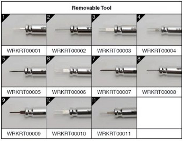
WRK II Removable Tools (WRKRT10000)
- Total 11 Removable Tools cover all 117 connectors

WRK II Cabinet Set (WRKCB60000)
- Twelve drawer cabinets X 6 EA with WRK all connectors Numbers

- Total 72 slots with enough space for 10 connectors in each slot except big size connectors

REWORK PROCEDURE
1. Use of WRKII Tool Set (GHWRK2T)
1. Disconnect the battery cable.

2. Choose the correct clamping slot for the wire and strip off the wire coat.

- If the incorrect crimping slot is used, the terminal may be damaged and may not fit into the connector.
2. Use of in-line solder (GHWRK2T-SDR01) and Shrink tube set (GHWRK2T-STS03, 05, 09, 12)

1. Strip off about 5mm of the wire coat at the end of the wires.

2. Insert each wire into the opposite ends of the in-line solder and crimp using a wire stripper.

3. Put the shrink tube over the connection area and shrink the tube using an electrical hot gun.

4. The shrink tube should be securely wrapped around the soldering area and exposed wiring.
3. Use of WRKII Removable Tool (WRKRT10000)
- Flat tip type : Removal of single locking male/female terminal from the connector

1. Remove the front or rear retainer (holder, stopper) of the connector.

2. Ensure that the tip of the tool is inserted into the gap between the elastic arm of key and terminal.

3. Remove the terminal and check the terminal condition, if it is damaged, replace it with a new terminal

- Double tip type : Removal of double locking male/female terminal from the connector.
- WRK II Standard Kit "GHWRK2"
Total 117 connectors well designed to repair automotive wiring harness instead of whole parts with wiring harness replacement (1 set of connector = 5 connectors each)
- Effective to save the labor & parts cost and reduce time to complete the service on vehicle
WRKII Reference Service Tools
WRKII Tool Set (GHWRK2T)
WRK II Removable Tools (WRKRT10000)
- Total 11 Removable Tools cover all 117 connectors
WRK II Cabinet Set (WRKCB60000)
- Twelve drawer cabinets X 6 EA with WRK all connectors Numbers
- Total 72 slots with enough space for 10 connectors in each slot except big size connectors
REWORK PROCEDURE
1. Use of WRKII Tool Set (GHWRK2T)
1. Disconnect the battery cable.
2. Choose the correct clamping slot for the wire and strip off the wire coat.
- If the incorrect crimping slot is used, the terminal may be damaged and may not fit into the connector.
2. Use of in-line solder (GHWRK2T-SDR01) and Shrink tube set (GHWRK2T-STS03, 05, 09, 12)
1. Strip off about 5mm of the wire coat at the end of the wires.
2. Insert each wire into the opposite ends of the in-line solder and crimp using a wire stripper.
3. Put the shrink tube over the connection area and shrink the tube using an electrical hot gun.
4. The shrink tube should be securely wrapped around the soldering area and exposed wiring.
3. Use of WRKII Removable Tool (WRKRT10000)
- Flat tip type : Removal of single locking male/female terminal from the connector
1. Remove the front or rear retainer (holder, stopper) of the connector.
2. Ensure that the tip of the tool is inserted into the gap between the elastic arm of key and terminal.
3. Remove the terminal and check the terminal condition, if it is damaged, replace it with a new terminal
- Double tip type : Removal of double locking male/female terminal from the connector.
Factory Service Tools
Use the Manual With the Right Hardware
Pair factory procedures with proven DIY tools so the instructions are easier to execute.
Disclosure: Verified tool recommendations may earn an affiliate commission at no cost to you.
When to See a Mechanic
Stop DIY work and contact a certified mechanic immediately if any of the following apply:
- • You smell fuel, burning insulation, or see smoke.
- • Brakes feel soft, pull hard to one side, or make grinding noises.
- • The engine overheats, stalls repeatedly, or misfires under load.
- • You are missing required tools, torque specs, or safe lifting equipment.
- • You are not confident in the next step or safety outcome.