
Safety Warning
DIY auto repair can cause serious injury, fire, or vehicle damage. These guides are for informational purposes only. Always follow OEM torque specs, wear PPE, and consult a certified mechanic if you are unsure. You are solely responsible for your safety.
2006 Hyundai Azera V6-3.8LFACTORY OEM SERVICE PROCEDURE
Timer/Control Unit: Testing and Inspection
INSPECTION
Trouble diagnostics when using scan tool.
1. If the self-diagnostic function is in operation, CAN communication stops and LIN communication is converted into self-diagnostic communication.
2. Only BCM communicates directly with scan tool, and the other units perform self-diagnostic function by BCM through the mediator of CAN or LIN.
BCM CURRENT DATA
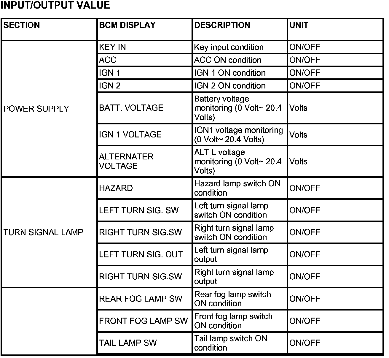

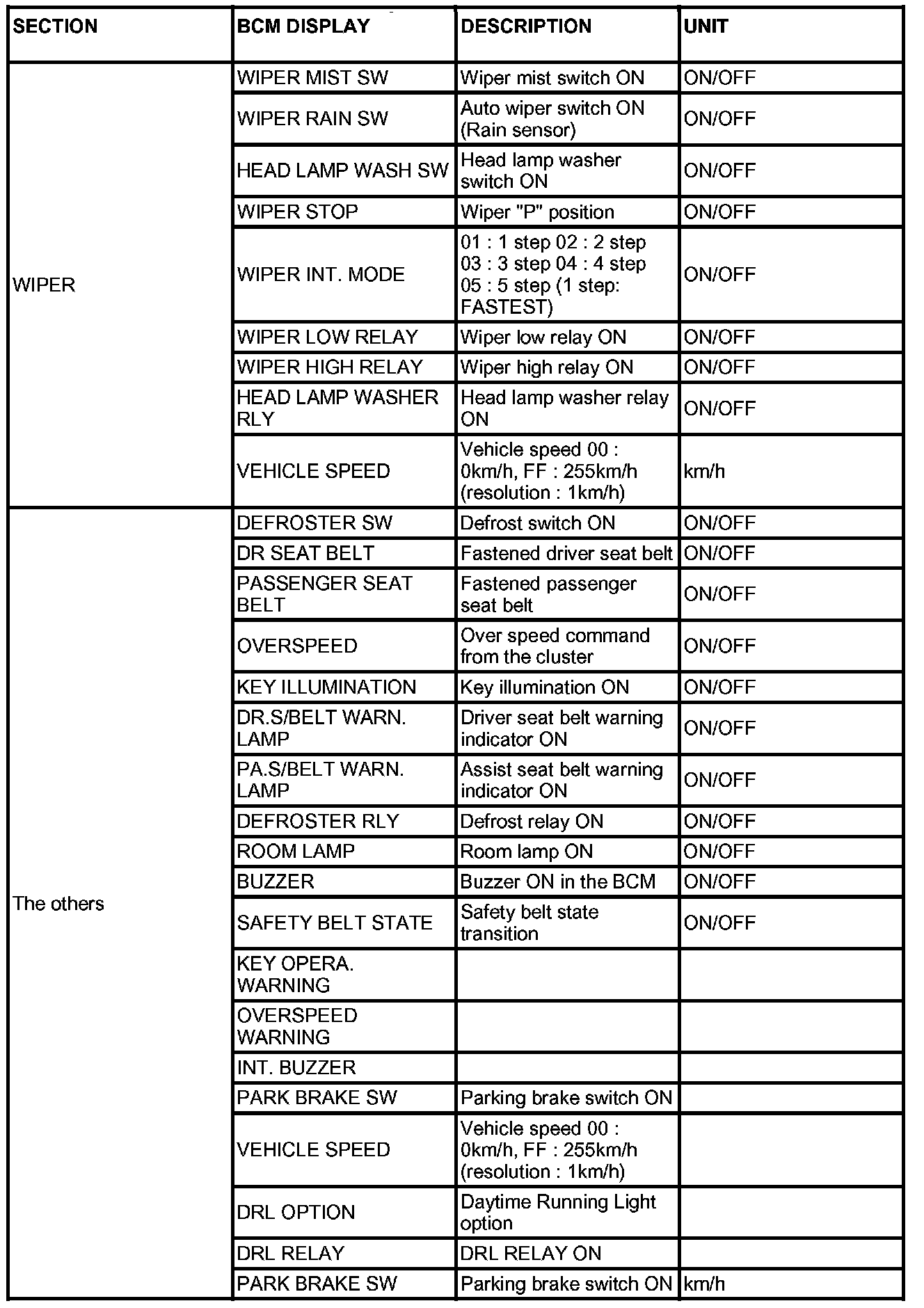

The body control module can diagnose with the diagnosis tool more quickly. The BCM communicates with the diagnosis tool and then reads the input/output value and drives the actuator.

SELF DIAGNOSIS : BCM DTC LIST
BCM ACTUATOR OPERATION

SCAN tool can operates all actuators controlled by BCM by force.
ADM, DDM, IMS SELF DIAGNOSTIC FUNCTION

1. It can be communicated with scan tool through of BCM.
2. BCM receives the commands from scan tool and remits to DDM, ADM and IMS units with CAN. BCM receives the response from the units with CAN inversely, and feedback to scan tool with CAN.
3. Input display and output forced drive can be performed in each of DDM, ADM and IMS units. Though, failure diagnosis is limited to the certain diagnosis ranges.


DRIVER DOOR MODULE (DDM)


ASSIST DOOR MODULE (ADM)


POWER SEAT MODULE (IMS)


TILT & TELESCOPE MODULE (IMS)
Trouble diagnostics when using scan tool.
1. If the self-diagnostic function is in operation, CAN communication stops and LIN communication is converted into self-diagnostic communication.
2. Only BCM communicates directly with scan tool, and the other units perform self-diagnostic function by BCM through the mediator of CAN or LIN.
BCM CURRENT DATA
Input/Output Value (Part 1):
Input/Output Value (Part 2):
Input/Output Value (Part 3):
Input/Output Value (Part 4):
The body control module can diagnose with the diagnosis tool more quickly. The BCM communicates with the diagnosis tool and then reads the input/output value and drives the actuator.
Self Diagnosis : BCM DTC List:
SELF DIAGNOSIS : BCM DTC LIST
BCM ACTUATOR OPERATION
BCM Actuator Operation:
SCAN tool can operates all actuators controlled by BCM by force.
ADM, DDM, IMS SELF DIAGNOSTIC FUNCTION
1. It can be communicated with scan tool through of BCM.
2. BCM receives the commands from scan tool and remits to DDM, ADM and IMS units with CAN. BCM receives the response from the units with CAN inversely, and feedback to scan tool with CAN.
3. Input display and output forced drive can be performed in each of DDM, ADM and IMS units. Though, failure diagnosis is limited to the certain diagnosis ranges.
Driver Door Module (DDM) - Input/Output Value (Part 1):
Driver Door Module (DDM) - Input/Output Value (Part 2):
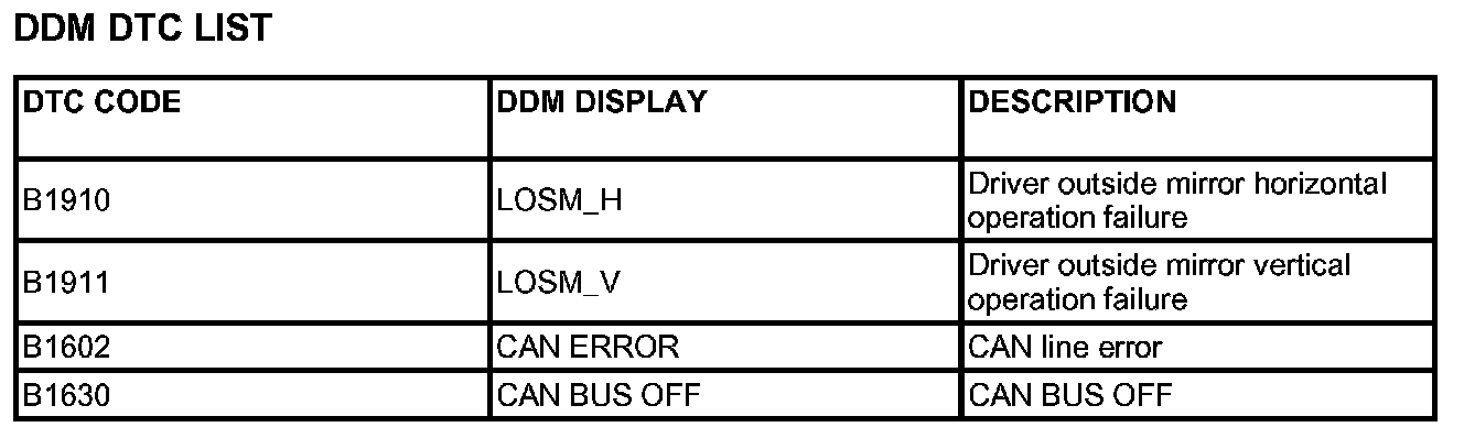
DDM DTC List:
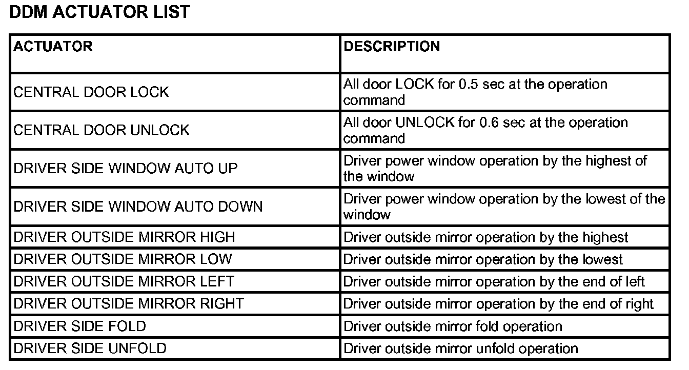
DDM Actuator List:
DRIVER DOOR MODULE (DDM)
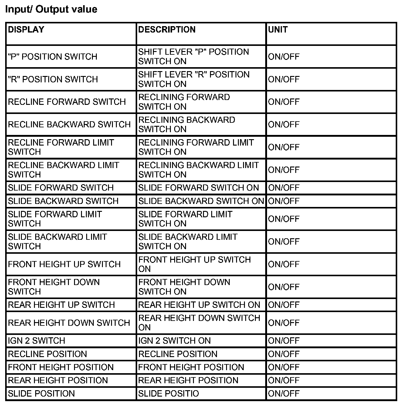
Assist Door Module (ADM) - Input/Output Value:
ADM DTC List:
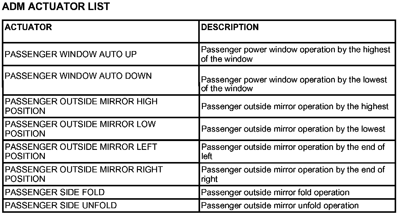
ADM Actuator List:
ASSIST DOOR MODULE (ADM)
Power Seat Module (IMS) - Input/Output Value:
IMS DTC List:
IMS Actuator List:
POWER SEAT MODULE (IMS)
Tilt & Telescope Module (IMS) - Input/Output Value:
TILT DTC List:
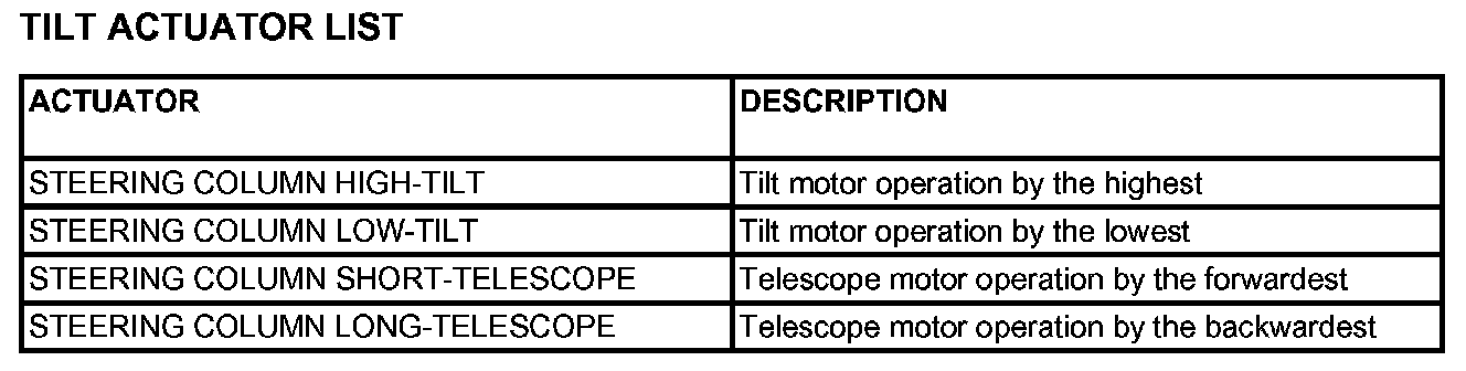
TILT Actuator List:
TILT & TELESCOPE MODULE (IMS)
Factory Service Tools
Use the Manual With the Right Hardware
Pair factory procedures with proven DIY tools so the instructions are easier to execute.
Disclosure: Verified tool recommendations may earn an affiliate commission at no cost to you.
When to See a Mechanic
Stop DIY work and contact a certified mechanic immediately if any of the following apply:
- • You smell fuel, burning insulation, or see smoke.
- • Brakes feel soft, pull hard to one side, or make grinding noises.
- • The engine overheats, stalls repeatedly, or misfires under load.
- • You are missing required tools, torque specs, or safe lifting equipment.
- • You are not confident in the next step or safety outcome.