
Safety Warning
DIY auto repair can cause serious injury, fire, or vehicle damage. These guides are for informational purposes only. Always follow OEM torque specs, wear PPE, and consult a certified mechanic if you are unsure. You are solely responsible for your safety.
2001 Hyundai Santa Fe L4-2.4LFACTORY OEM SERVICE PROCEDURE
Timer/Control Unit: Testing and Inspection
While operating the components, check whether the operations are normal with timing chart.
ETACS FUNCTION

1. Vehicle speed sensing intermittent wiper
Time specification
T1: Max. 0.5 sec.
T2: 0.6 - 0.7 sec. (Time of wiper motor 1 rotation)
T3: At vehicle speed 0 km/h.
2.6 ± 0.7 sec. (VR - 0 kOhm) - 18.0 ± 1 sec (VR = 50 kOhm)
At vehicle speed = 100 km/h or more.
1.0 ± 0.2 sec (VR = 0 kOhm) - 10.0 ± 1 sec (VR = 50 kOhm)

2. Washer
a. Time specification
T1: 0.7 sec.
T2: 2.5 - 3.8 sec.
b. This function should be operated preferentially even though the variable intermittent wiper is operating.
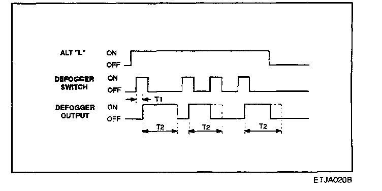
3. Rear window defogger
Time specification
T1: 60 msec
T2: 20 ± 1 min.

4. Seat belt warning
Time specification
T1: 6 ± 1 sec.
T2: 0.45 ± 0.1 sec.
T3: 0.3 ± 0.1 sec.

5. Ignition key hole illumination
Time specification
T1 : 10 ± 1 sec.
T2: 0 - 10 sec.
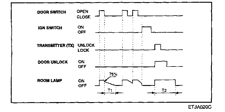
6. Delayed out room lamp
Time specification
T1 : 5.5 ± 0.5 sec.
T2: 30 ± 2 sec.

7. Key operated warning
Time specification
T1, T2: 0.45 ± 0.1 sec.

8. Ignition key reminder
Time specification
T1: 0.5 sec.
T2: 1 sec.
T3: 0.5 sec., 3 times

9. Tail lamp auto cut
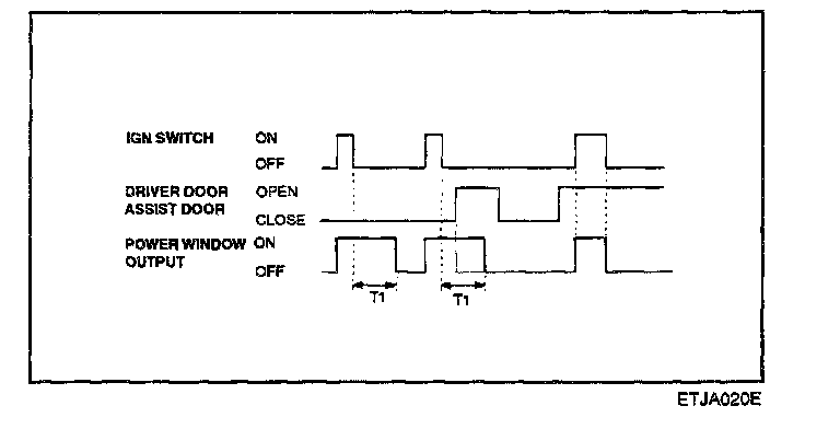
10. Power window timer
Time specification
T1 : 30 ± 3 sec.

11. Central door lock/unlock
Time specification
T1 : 0.5 ± 0.1 sec.

12. Crash door unlock
Time specification
T1 : 200 ms
T2: 40 ms
T3: 5 ± 0.5 sec.

13. Parking start warning
Time specification
T1 : 2.5 ± 0.5 sec
T2 : 0.3 ± 0.1 sec
ANTI-THEFT FUNCTION

1. Arm function
Time specification
T1: 0.5 sec.
T2: Max 2 sec.
T3: 1.0 ± 0.2 sec.
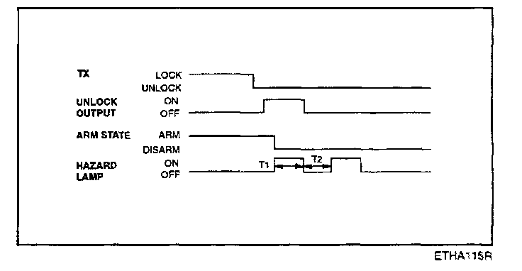
2. Disarm function
Time specification
T1, T2: 0.5 ± 0.1 sec.
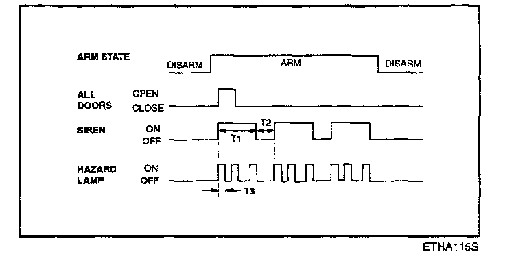
3. Alarm function
a. Time specification
T1: 27 ± 2 sec.
T2: 10 ± 1 sec.
T3: 0.5 ± 0.1 sec.
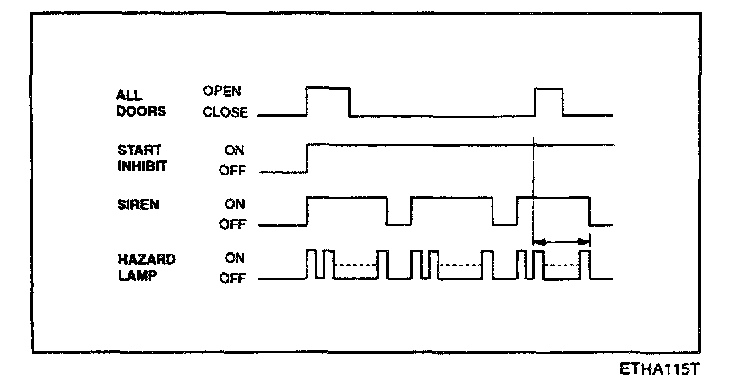
b. New alarm occurs while the alarm is sounding.
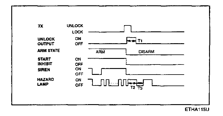
c. Disarmed with TX (Transmitter) while the alarm is sounding.
Time specification
T1, T2, T3: 0.5 ± 0.1 sec.
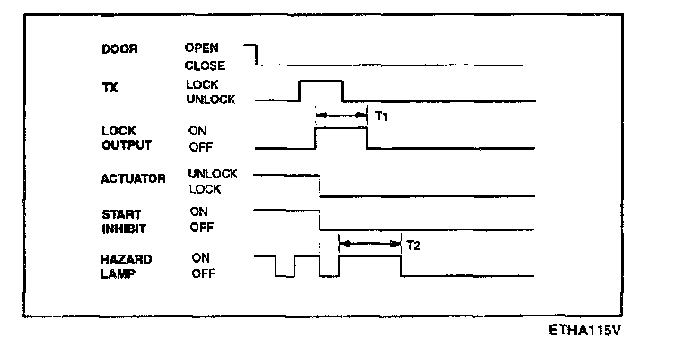
d. TX (Transmitter) lock button pressed when the door closed while the alarm is sounding.
Time specification
T1 : 0.5 sec.
T2 : 1.0 ± 0.2 sec.
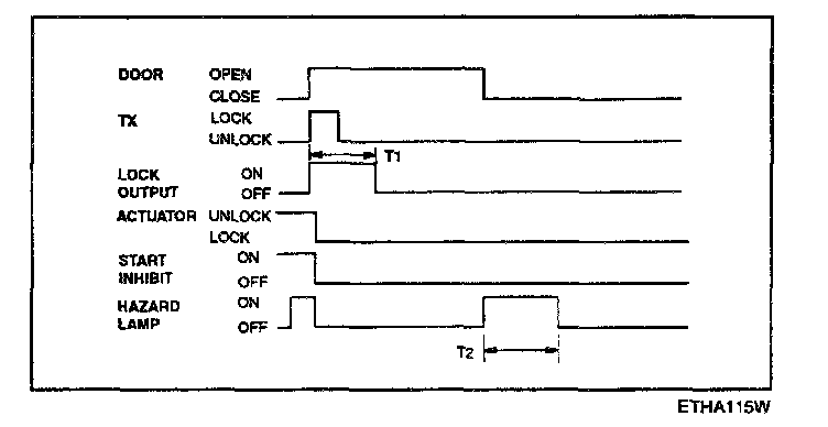
e. TX (Transmitter) lock button pressed when the door opened while the alarm is sounding.
Time specification
T1 : 0.5 sec.
T2 : 1.0 ± 0.2 sec.
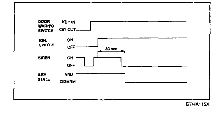
f. Disarmed after 30 sec when the ignition switch is turned on while the alarm is sounding.

g. Start inhibit is "ON" regardless of door latch lock state.

h. Battery is disconnected during the alarm state.
4. Code saving method.
a. Remove the lower crash panel.
NOTE: Don't disconnect the negative (-) battery terminal.

b. To store new codes
- Activate the keyless entry/receiver unit and change the code saving switch of the receiver unit from "OFF" to "SET".
- The secret codes from the transmitter will be stored into the receiver unit when the door lock button or unlock button is pressed on the transmitter.
- Save the 2nd transmitter codes in the same manner.
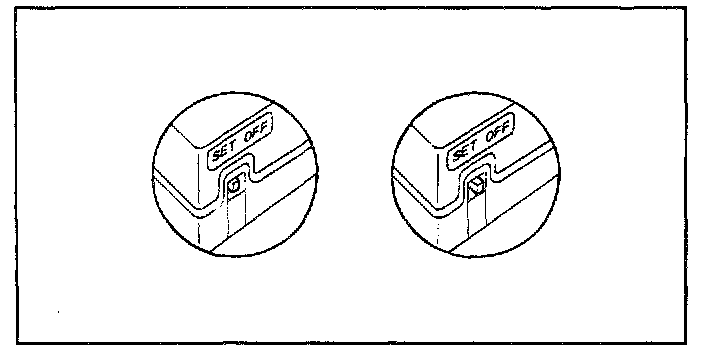
c. Return the code saving switch of the receiver unit from "SET" to "OFF".
d. Install the lower crash panel.
ETACS FUNCTION
1. Vehicle speed sensing intermittent wiper
Time specification
T1: Max. 0.5 sec.
T2: 0.6 - 0.7 sec. (Time of wiper motor 1 rotation)
T3: At vehicle speed 0 km/h.
2.6 ± 0.7 sec. (VR - 0 kOhm) - 18.0 ± 1 sec (VR = 50 kOhm)
At vehicle speed = 100 km/h or more.
1.0 ± 0.2 sec (VR = 0 kOhm) - 10.0 ± 1 sec (VR = 50 kOhm)
2. Washer
a. Time specification
T1: 0.7 sec.
T2: 2.5 - 3.8 sec.
b. This function should be operated preferentially even though the variable intermittent wiper is operating.
3. Rear window defogger
Time specification
T1: 60 msec
T2: 20 ± 1 min.
4. Seat belt warning
Time specification
T1: 6 ± 1 sec.
T2: 0.45 ± 0.1 sec.
T3: 0.3 ± 0.1 sec.
5. Ignition key hole illumination
Time specification
T1 : 10 ± 1 sec.
T2: 0 - 10 sec.
6. Delayed out room lamp
Time specification
T1 : 5.5 ± 0.5 sec.
T2: 30 ± 2 sec.
7. Key operated warning
Time specification
T1, T2: 0.45 ± 0.1 sec.
8. Ignition key reminder
Time specification
T1: 0.5 sec.
T2: 1 sec.
T3: 0.5 sec., 3 times
9. Tail lamp auto cut
10. Power window timer
Time specification
T1 : 30 ± 3 sec.
11. Central door lock/unlock
Time specification
T1 : 0.5 ± 0.1 sec.
12. Crash door unlock
Time specification
T1 : 200 ms
T2: 40 ms
T3: 5 ± 0.5 sec.
13. Parking start warning
Time specification
T1 : 2.5 ± 0.5 sec
T2 : 0.3 ± 0.1 sec
ANTI-THEFT FUNCTION
1. Arm function
Time specification
T1: 0.5 sec.
T2: Max 2 sec.
T3: 1.0 ± 0.2 sec.
2. Disarm function
Time specification
T1, T2: 0.5 ± 0.1 sec.
3. Alarm function
a. Time specification
T1: 27 ± 2 sec.
T2: 10 ± 1 sec.
T3: 0.5 ± 0.1 sec.
b. New alarm occurs while the alarm is sounding.
c. Disarmed with TX (Transmitter) while the alarm is sounding.
Time specification
T1, T2, T3: 0.5 ± 0.1 sec.
d. TX (Transmitter) lock button pressed when the door closed while the alarm is sounding.
Time specification
T1 : 0.5 sec.
T2 : 1.0 ± 0.2 sec.
e. TX (Transmitter) lock button pressed when the door opened while the alarm is sounding.
Time specification
T1 : 0.5 sec.
T2 : 1.0 ± 0.2 sec.
f. Disarmed after 30 sec when the ignition switch is turned on while the alarm is sounding.
g. Start inhibit is "ON" regardless of door latch lock state.
h. Battery is disconnected during the alarm state.
4. Code saving method.
a. Remove the lower crash panel.
NOTE: Don't disconnect the negative (-) battery terminal.
b. To store new codes
- Activate the keyless entry/receiver unit and change the code saving switch of the receiver unit from "OFF" to "SET".
- The secret codes from the transmitter will be stored into the receiver unit when the door lock button or unlock button is pressed on the transmitter.
- Save the 2nd transmitter codes in the same manner.
c. Return the code saving switch of the receiver unit from "SET" to "OFF".
d. Install the lower crash panel.
Factory Service Tools
Use the Manual With the Right Hardware
Pair factory procedures with proven DIY tools so the instructions are easier to execute.
Disclosure: Verified tool recommendations may earn an affiliate commission at no cost to you.
When to See a Mechanic
Stop DIY work and contact a certified mechanic immediately if any of the following apply:
- • You smell fuel, burning insulation, or see smoke.
- • Brakes feel soft, pull hard to one side, or make grinding noises.
- • The engine overheats, stalls repeatedly, or misfires under load.
- • You are missing required tools, torque specs, or safe lifting equipment.
- • You are not confident in the next step or safety outcome.